Hi,
I have 2 ECC99s for 2 channels, which means I have a pair of triodes sitting around unused. My initial idea of paralleling them to increase gain was aborted quickly when I learnt that it didn't work that way. The triodes that are in use are CCS loaded, so I don't want to try SRPP or mu stage. I was thinking of things I could do with those triodes, and wondered if a diff amp would make sense? I'd lose gain, which won't be good, I don't have much gain to spare. But would I gain anything? Would my PSRR increase much over what the CCS load gives me right now? Is this worth pursuing?
Any other ideas for using the two spare triodes?
Thanks,
Saurav
Hi,
It doesn't work that way...
BUT it halves impedances, noise and doubles transconductance, the latter is a nice bonus but requires good matching so no current hogging occurs.
Cheers,")
My initial idea of paralleling them to increase gain was aborted quickly when I learnt that it didn't work that way.
It doesn't work that way...
BUT it halves impedances, noise and doubles transconductance, the latter is a nice bonus but requires good matching so no current hogging occurs.
Cheers,
Any other ideas for using the two spare triodes?
Quote: Any other ideas for using the two spare triodes?
Well,what about using them to condition your supply up..,by making two (seperate for each channel)shunt-regulators?Good to do with those two *spares*.
It probably helps you to lower the capacity on the supply,thus reducing phaseshift.
Or u use them as kathode loads,when you can make a negative rail to it?
Just thinking out loud...
Have a nice day!
Hmm... I hadn't made the connection between triodes and shunt regulators. That could be an interesting idea. This obviously wouldn't be as straightforward as a VR tube, right, I'd have to build a regulator circuit around the triodes.
I'm not sure I understand what you mean by a cathode load.
And also increases input capacitance, which given the fact that I'm driving this with a passive linestage, may be the overriding factor.
It did sound a little smoother/softer with the paralleled triodes though. Not sure what factors contributed to it. One possibility would be the increased heater current draw, which brought the voltage down closer to 6.3V (it was around 7.1V without the spare triodes being turned on).
I'm not sure I understand what you mean by a cathode load.
BUT it halves impedances, noise and doubles transconductance, the latter is a nice bonus but requires good matching so no current hogging occurs.
And also increases input capacitance, which given the fact that I'm driving this with a passive linestage, may be the overriding factor.
It did sound a little smoother/softer with the paralleled triodes though. Not sure what factors contributed to it. One possibility would be the increased heater current draw, which brought the voltage down closer to 6.3V (it was around 7.1V without the spare triodes being turned on).
Hi,
Certainly...
Add to that the cable capacitance and it sure will roll off the highs.
One way of burning tubes like candles it to run them at too high heather voltages...
It will sound great for a while but you're just exhausting the cathode at an accellerated rate.
Any tube tester will show you that...
In fact I bet those tubes already are at 50% as it is now...
Cheers,
And also increases input capacitance, which given the fact that I'm driving this with a passive linestage, may be the overriding factor.
Certainly...
Add to that the cable capacitance and it sure will roll off the highs.
which brought the voltage down closer to 6.3V (it was around 7.1V without the spare triodes being turned on).
One way of burning tubes like candles it to run them at too high heather voltages...
It will sound great for a while but you're just exhausting the cathode at an accellerated rate.
Any tube tester will show you that...
In fact I bet those tubes already are at 50% as it is now...
Cheers,
Hi,
Once I did a test running a 6DJ8 at 7V heater supply...It took no more than a few minutes to bring cathode emission down to 80% of a new tube.
Once it's down, it wont come back up...that much I can tell you.
Sorry to bring the bad news...If you have, or have a friend with a tube tester you can have your tubes checked for emission.
Cheers,
How long does it take for the tube's life/emission to go down when operating at elevated heater voltages?
Once I did a test running a 6DJ8 at 7V heater supply...It took no more than a few minutes to bring cathode emission down to 80% of a new tube.
Once it's down, it wont come back up...that much I can tell you.
Sorry to bring the bad news...If you have, or have a friend with a tube tester you can have your tubes checked for emission.
Cheers,
Wow. That's not good news. I don't know anyone locally with a tube tester, but I'll keep that in mind.
Maybe this means it's time to try the 6C45-pi My CCS boards are set for 20mA so that should be fine, just need cathode resistors for 9V and I already have the capacitor. Or try 9V batteries like the 4V batteries I'm using now. I'll get some extra gain too.
How does one hook those tubes up? 100 ohm grid stoppers close up against each grid pin, and then connect the other ends of those resistors together and that goes to the input RCA? I think that's what I remember reading. And what about the multiple cathode pins - connect them all, or use any one?
Maybe this means it's time to try the 6C45-pi
My CCS boards are set for 20mA so that should be fine, just need cathode resistors for 9V and I already have the capacitor. Or try 9V batteries like the 4V batteries I'm using now. I'll get some extra gain too.How does one hook those tubes up? 100 ohm grid stoppers close up against each grid pin, and then connect the other ends of those resistors together and that goes to the input RCA? I think that's what I remember reading. And what about the multiple cathode pins - connect them all, or use any one?
Saurav said:Hmm... I hadn't made the connection between triodes and shunt regulators. That could be an interesting idea. This obviously wouldn't be as straightforward as a VR tube, right, I'd have to build a regulator circuit around the triodes.
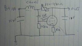
yep it's quite simple too...see attachment...look at Rk,and the two possible connections...see (hear) what's the differance...it works fine with any tube as long as you keep it within it's ratings ofcourse
and:Originally posted by Saurav I'm not sure I understand what you mean by a cathode load.
Well instead of a kathode resistor you can use a triode at the bottom but you'll need an negative rail to do so...i would stick to the shunt (regulation) buzzkiller...
Attachments
Hi,
Yes, that's one way of tackling it and you could apply the same method for the cathode connections.
If you have a scope you can keep the gridstopper's total value to a minimum...You want to listen to the tube, not the resistors.
Cheers,
How does one hook those tubes up? 100 ohm grid stoppers close up against each grid pin, and then connect the other ends of those resistors together and that goes to the input RCA?
Yes, that's one way of tackling it and you could apply the same method for the cathode connections.
If you have a scope you can keep the gridstopper's total value to a minimum...You want to listen to the tube, not the resistors.
Cheers,
Hi,
Universum,
What you're proposing is what is called a "Ripplekiller".
As you describe it it injects the ripple from the PS into the grid of the triode and you then take it of the plate out phase where it mostly cancels out.
What you don't mention is that this cause a voltage drop in the PS...No free lunch in electronics.
Cheers,
I have a kind of ripple reduction thing in there already, the cap from B+ to cathode described in Tubecad. I need to get better caps for that and the cathode bias cap on the 2A3. The noise/hum level isn't too bad now, I don't really care as long as it's inaudible from my listening position during late night listening.
So will the triode provide any voltage regulation, or is this just a hum reduction circuit?
I don't have a cathode resistor now, I have a battery under the cathode. Thanks for the idea though, that's not something I'd thought about.
Frank, I understand what you mean about keeping the resistors as low as possible. I think, anyway I have a 100MHz scope, and it isn't too good when the timebase is turned all the way up. Nevertheless, I've used it to get a general feel for the level of hash in the circuit (just looking at the fuzziness of the trace), and maybe I can use that to determine oscillations on the tube in a similar way.
So will the triode provide any voltage regulation, or is this just a hum reduction circuit?
I don't have a cathode resistor now, I have a battery under the cathode. Thanks for the idea though, that's not something I'd thought about.
Frank, I understand what you mean about keeping the resistors as low as possible. I think, anyway
I have a 100MHz scope, and it isn't too good when the timebase is turned all the way up. Nevertheless, I've used it to get a general feel for the level of hash in the circuit (just looking at the fuzziness of the trace), and maybe I can use that to determine oscillations on the tube in a similar way.Hi,
Know what ya mean...Pretty clever trick.
Nah...It reduces ripple.
Since there's no voltage reference and comparator it can't track anything but it provides some extra isolation from the B+ nonetheless, not a bad thing to have.
I could explain in detail but I think you got the picture already.
Sure, you can use that scope for that.
Cheers,
I have a kind of ripple reduction thing in there already, the cap from B+ to cathode described in Tubecad.
Know what ya mean...Pretty clever trick.
So will the triode provide any voltage regulation, or is this just a hum reduction circuit?
Nah...It reduces ripple.
Since there's no voltage reference and comparator it can't track anything but it provides some extra isolation from the B+ nonetheless, not a bad thing to have.
I could explain in detail but I think you got the picture already.
and maybe I can use that to determine oscillations on the tube in a similar way.
Sure, you can use that scope for that.
Cheers,
- Status
- This old topic is closed. If you want to reopen this topic, contact a moderator using the "Report Post" button.
- Home
- Amplifiers
- Tubes / Valves
- Diff amp driver -> SE output