Hi fellow forumers
I'm going to restore this amp for a friend of mine
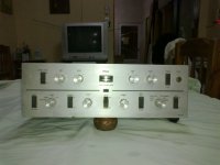
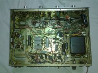
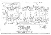
this is the unit: AM-240 Ampl/Mixer Olson Radio Corporation; Akron, Ohio, buil
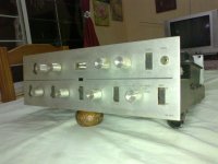
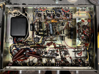
Obviously, the one I've in the bench is not in such a good shape, take a look:
Well, lacking the schematic the restoring job, while not impossible, becomes considerable more difficult. So If one good soul can share the circuit, it will help in an just and heroic cause.
Cheers
J.
I'm going to restore this amp for a friend of mine
this is the unit: AM-240 Ampl/Mixer Olson Radio Corporation; Akron, Ohio, buil
Obviously, the one I've in the bench is not in such a good shape, take a look:
Well, lacking the schematic the restoring job, while not impossible, becomes considerable more difficult. So If one good soul can share the circuit, it will help in an just and heroic cause.
Cheers
J.
Attachments
addendum:
first and dirt measurements confirm that this circuit output stage works with 415V on plates, 400V on G2, and -20V fixed bias.
First decision: revolve heaven and earth to find the original 7189 tubes (a very difficult and expensive task in my neighborhood), or derate the B+ to a more maneageable level, in order to fit the humble 6BQ5's (standard flavour)?.
Since this unit is being powered through a 110 to 220 step down transformer, a proper 220V PT is likely to be purchased, so, adjusting to fit different tubes will not be a problem, but...
Jim McShane ships world wide and it's likely other reliable tube sellers can accommodate you too.
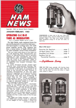
Fortunately, a good and affordable 7189 equivalent is in production. It's the Russian 6П14П-EB (6p14p-ev), AKA EL84M, is what you should buy.
Be careful to distinguish between the 7189 and the 7189A. 7189As are extinct and amps using it need socket rework and (perhaps) operating conditions adjustment to employ the 6П14П-EB.
Thanks Infinia and Eli. Much appreciated.
This weekend I'm going to check the amp against the Scott schemo, it will be fun.
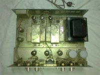
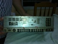
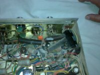
I'm mostly concerned about some rotary switches, cables were cut off, and functions disabled, a real mess, ad opera some shitty incompetent TV repairman , for sure.
For what I saw, the tubes fitted (one is missing) are standard 7189's, not the "A" version.
I guess I'll take the 6П14П-EB route... Now I'm looking for some tubes on Mercado Chifle, our local version of Steals Bay
This weekend I'm going to check the amp against the Scott schemo, it will be fun.
I'm mostly concerned about some rotary switches, cables were cut off, and functions disabled, a real mess, ad opera some shitty incompetent TV repairman , for sure.
For what I saw, the tubes fitted (one is missing) are standard 7189's, not the "A" version.
I guess I'll take the 6П14П-EB route... Now I'm looking for some tubes on Mercado Chifle, our local version of Steals Bay
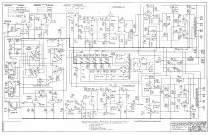
@Mosquito , please check the TRIO Kenwood W-46K is 98% identical to the Olson AM-240 . Indeed this Olson AM-240 is exactly the same as the Herald AM-13. Seems like those amplifiers were assembled in Japan, only few differences in terms on resistor values for gains and HUM control circuit. I have a Herald AM 240 and could not find the schematic until researched a little bit and found the Trio Kenwood looks like the same unit internally.
Attachments
Convert to 7591? Simple socket swap.revolve heaven and earth to find the original 7189 tubes
Thank You so much, this info is pure gold.@Mosquito , please check the TRIO Kenwood W-46K is 98% identical to the Olson AM-240 . .. found the Trio Kenwood looks like the same unit internally.
I own and enjoy an Olson AM-240. In my efforts to make it play, as it arrived DOA from EBay, I had to do some extensive parts upgrades. After weeks of trying, I finally got my AM-240 to sound. That was many years ago, like back in 2002-2003. Now Fast forward, I just pulled the AM-240 out of storage last week and the first thing that I did was to power it up using my Variac. One of the Power Supply Diodes was shorted, blew the fuse, and this happened the last time I used the AM-240 in my Garage in 2013, it also blew a fuse. So I replaced both Diodes with GP15M/1431 that are 1000PIV, 1,5A and the amp came alive again. Next, I connected the AM-240 amp to my 100W Stereo Dummy Load and looked at 1KHz on my Dual Trace Oscilloscope.... oh. As usual, for older amps, one channel had less power than the other, and the top end of the louder channel was clipping. I adjusted the balance Control to compensate and it sounded good over my speakers when I put the AM-240 on duty, the distorting channel now behaved. But I was curious about the Channel imbalance, as this is a problem I have seen with many older Tube Preamps and Integrated Amps. On the AM-240, the Stereo Volume Control is not measuring well. One wafer was 1.23 Meg, the other was .882 Meg. This also happened on my Dynaco PAS3x where I was lucky to find a NOS Volume Control (out of production). I ordered a NOS 1 Meg Stereo Volume Pot with a Loudness Tap. The reason I post here on my AM-240 is that I had to sacrifice some of the internal stuff like the Headphone Circuit and also the Output Phase Switch to get it to play. I bypassed both of these, so that my Output Transformers are now directly connected to the 4-8-16-C terminals, getting rid of the extra stuff that I really do not need or want. Hey if anyone needs a DC voltage reading chart, I can provide it. The final thing, I get no sound from the Phono section, it was and still is totally DOA, I plan to eventually draw out the schematic on paper and also draw out the rest of the amplifier to share. Reverse Engineering will take a few month's, as AM-240 schematics are non-existent. How does the AM-240 sound? I like it very much. The sound is very full and has depth, good strong Bass, Midrange is very sweet and extended with great Treble. The Loudness button only works at low volumes, it is too brash and not really needed. The tubes that I use, are the Russian 7189 types as this Amp will roast EL-84's. I haven't tried the EL-84M yet but I suspect that they will not like the high plate voltage the AM-240 and 7189 amps of that period need, it is in the higher 390V to lower 420V range, and that is clearly out of EL-84 Plate Dissipation territory. One could possibly change the AM-240 to Cathode Bias and put some large Power Resistors in the PSU Voltage Divider, but this is not good, I have tried this brute force approach in the past with 7189 amps and the results were not good. If your AM-240 got totally roasted, a Hammond Power Transformer could rescue the amp, but I would go Cathode Bias to keep the effort simple. The tubes needed for the AM-240 are Russian 6p14pEV (a.k.a. 6p14pEB) and also the 6p14pER. These Tubes sound great and can take up to 450V on the Plates.
If I ever find a AM-240 schematic I will share it immediately, in the meantime I am available to help get youre up an running.
If I ever find a AM-240 schematic I will share it immediately, in the meantime I am available to help get youre up an running.
With 415V on the plate, and 400V on g2, the 6BQ5 and EL84 are very poor substitutes. Get out the fire extinguisher, just in case.
This is not a guitar amplifier at a rock concert with fireworks (you might set them off early). That would be a case of thermal run-away.
The 7591 filament takes 0.8A, the 7189 takes 0.76A, even with 4 filaments, that is close enough.
But changing from a Noval 9 pin socket to an 8 pin Octal socket is not easy . . . you need extra room, and it is hard work with a chassis punch on hardened steel.
Have fun restoring, and listening!
Unfortunately I did not take a photo of a roasted AM-240 that I bought for parts, I dumped the chassis in the recycle center. That AM240 must have been used with EL-84 as some 7189 amps of the day suffered the same death. As you said, both Output Transformers were Charcoal Black inside, likely from a Motley Crue show. That AM240 was a good donor amp for Knobs, Top Cover and Bottom Cover. Hey I would not put 7591 inside an AM240, maybe 7868 would be a better fit, 6GM5 would work better as the 9 pin sockets would not need removal, I will think about your suggestion. Although the Primary P-P Impedance of the OPT might be in the ballpark I will sine wave test and see if it is in the 7000-8000 Ohms range. You can see my work on the AM240 at https://www.shermanaudio.com, I will post more photos of the amp once I upgrade the Volume Control. These old Japanese amps are a challenge, the Suzuki PIO caps all dry out, and they take lots of parts to get them to play safely. These are great amps for a small den.
Last edited:
Just curious . . . what is the measured dissipation?it is in the higher 390V to lower 420V range, and that is clearly out of EL-84 Plate Dissipation territory.
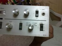
I just saw your question. Will do the measurement tonight and post the results. The AM-240 is fixed bias so I only need to measure the Plate Voltage to ground. Now as far as the plate current, I will need to unsolder the Cathode and insert a Milliammeter, I will look at this to see how intrusive it will be. I can install two Tip-Jacks and use a SPST switch to be able to measure in the future. Here is a photo of my AM-240 last night with the new 1 Meg stereo pot. Sounding good to me.

I measured the AM-240 and took down readings. The line voltage at my home is 118 VAC. as measured by my Fluke 87V True RMS Multimeter
")
For each pair of 7189 (Russian 6p14pEB) Tubes, the amp actually uses a 30 Ohm Resistor to ground. I had not noticed this before, as I had never really made a measurement chart. So... the Plate Voltage on the Power Tubes Pin 7 = 434 VDC. The Plate Current through each Tube is calculated by measuring the DC Voltage across the 30 Ohm Resistor. That Voltage measured 1.44 VDC. Therefore the Current through each pair of Power Tubes is 1.44vdc/ 30 Ohms = 0.048 amps, or roughly 50 Milliamps per pair. So each Power Tube draws 24 milliamps. The plate dissipation is therefore P = VI. Where V = 434 VDC and I = 0.024 A = 10.41 Watts, of course the 30 Ohm resistor is taking some of that heat as well, but it is quite small, So the Tubes are running at a HOT 434 VDC and the Plates are dissipating roughly 10.5 Watts if the amp is plugged into 120 VDC. The PA Max for a EL84/6BQ5 is 12 Watts, so these are just 1.5 watts under the absolute limit. What really cooks the EL84's is the combination of the Plate Voltage and Plate Current. The maximum plate voltage for the 6BQ5/EL84 is 300 VDC, and maybe pushing it to 320 VDC in some amps. But at 434 VDC the 6BQ5/EL84 are stressing out because of the inter-electrode leakage current that is likely why these amps will burn through EL84's in a few hours. I have not tried EL84's in the AM-240 and do not plan to do so. Thoughts and commennts are very welcome. On a positive note the Phono Stage tubes do not have any DC Voltages so there is a problem. I never hooked up a Turntable, but if I do, I will note get any sound. Time to trace some wires and see why the Phono Stage Tubes are only lighting up... but no Plate Voltages at all. I will post the Voltage Chart next when I clean it up a bit and hopefully add the Phono stage tubes when I can see why they are not measuring any DC on the pins. Hope this answers the question...Just curious . . . what is the measured dissipation?
Attached are my Voltage and Bias readings for my AM-240. I see that the Phono Stage cathodes are tied to ground so the Grids of the 12AX7's must have the bias voltage. I did not measure that but plan to try to sketch out the AM-240 Schematic on mt free time. It will be labor intensive but worth it as this schematic was not circulated. Not even a Sams Photofact....
Attachments
BTW the Phono Stage has an open 100K Suzuki Resistor that completely killed the DC HV to those tubes. Once I replaced that and also a funny 200K Suzuki to the rear 12AX7, the Phono Stage sounds great, it has a chunky character, brings the cheap conical cartridge on my Test Bench old Technics P-Mount to life. I finally have the Phono Stage operating, it had never worked.... I don't often find open resistors, but this time I did.
So I now that I finally measured the AM-240 and not just estimated things, I ask the same old question that I come across many audio forums; Can a 6BQ5/EL-84 operate with 430 Volts on the Plate? If the Plate Current is kept below the 12 Watt Dissipation limit? There seems to be some consensus that as long as the Plate Dissipation is kept below 12 Watts by reducing the Plate Current, the Voltage on the 6BQ5/EL84 can go up as high as 450 VDC? My best guess and as I stated above, there are other electrical parameters that could be to the detriment of a Tube with boosted Plate Voltage above spec. Could Grid Leakage could also be affected by boosting Plate Voltage? Heater to Cathode Voltage is another spec that is compensated by "floating" the Filament AC Voltage with a DC Bias to keep SRPP Topologies in the safe Heater to Cathode zone.
I am curious as I once worked on a Mesa Boogie 50 Caliber, and that Amp ran the EL-84's at 420 VDC using Cathode Bias, I don't recall the Cathode Current now as it was back in 2010.
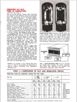
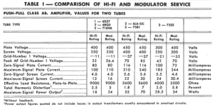
The Chart below for the 7189 shows 400V Max, with -15 Grid and 15 Milliamps, well below the 12 Watt Plate Dissipation at 400v x 0.015a = 6 Watts. But the AM-240 runs these at 434v x .024a =10.5 watts, likely seeking more power, at less tube life? Maybe the 7189 is just an 6BQ5/EL-84 manufactured with better materials to last longer under punishment?
Or maybe Tube Datasheets are just "general guidelines" with limits that interact and can be exceeded, as long as the Plate Dissipation is not over the rated limit, meaning that the true limit is the Total Plate and Grid Dissipations added together while the other limits are to be kept within sanity, meaning I would not put 600 V on the plate of a 6BQ5/EL-84 even if I adjusted the Bias to a Plate Current below 12 Watts?
I would love comments and perspective on this topic that I find very interesting.

I am curious as I once worked on a Mesa Boogie 50 Caliber, and that Amp ran the EL-84's at 420 VDC using Cathode Bias, I don't recall the Cathode Current now as it was back in 2010.
The Chart below for the 7189 shows 400V Max, with -15 Grid and 15 Milliamps, well below the 12 Watt Plate Dissipation at 400v x 0.015a = 6 Watts. But the AM-240 runs these at 434v x .024a =10.5 watts, likely seeking more power, at less tube life? Maybe the 7189 is just an 6BQ5/EL-84 manufactured with better materials to last longer under punishment?
Or maybe Tube Datasheets are just "general guidelines" with limits that interact and can be exceeded, as long as the Plate Dissipation is not over the rated limit, meaning that the true limit is the Total Plate and Grid Dissipations added together while the other limits are to be kept within sanity, meaning I would not put 600 V on the plate of a 6BQ5/EL-84 even if I adjusted the Bias to a Plate Current below 12 Watts?
I would love comments and perspective on this topic that I find very interesting.
You seem to have intuited (is that a word?) the purpose of my question.Or maybe Tube Datasheets are just "general guidelines" with limits that interact and can be exceeded, as long as the Plate Dissipation is not over the rated limit, meaning that the true limit is the Total Plate and Grid Dissipations added together while the other limits are to be kept within sanity, meaning I would not put 600 V on the plate of a 6BQ5/EL-84 even if I adjusted the Bias to a Plate Current below 12 Watts?
I would love comments and perspective on this topic that I find very interesting.
Though I'm certainly not an expert I've always considered dissipation to be the primary consideration, within reason, just as you say. I will say that I've used (American old production) 6BQ5s at over 400v in a Sherwood S-5000, which is very highly regarded. The Sherwood does run them conservatively in terms of dissipation.
Some claim that the Sherwood is hard on output tubes. If so, I think that has more to do with the fact that they are mounted very close together, and right next to the rectifier tube, all under a small "heat shield" that traps the heat. On the last one I restored the wiring in that area was so well toasted that I replaced it all with teflon insulated military spec wire. Despite this, the 6BQ5s certainly don't get burned up in a few hours and seem to last reasonably well despite the ventilation issue. That amp came to me with a well used set of 6BQ5s and they still tested good. I suspect they had been in the amp for a good long time.
I've posted about this in some detail elsewhere. For example see post #24 here:
https://www.audiokarma.org/forums/i...ith-heathkit-iron.978436/page-2#post-15711356
Attachments
Last edited:
- Home
- Amplifiers
- Tubes / Valves
- Olson AM-240 schematic needed