TINA doesn't like that syntax. Try this one. Copy and paste this into notepad and save it with a .cir or .lib extension, i.e. "12AX7.cir".as for TINA
I got up to here and then the next button stops working. Should I just exit the window and search for my 12ax7?
Code:
*
* Generic triode model: 12AX7
* Copyright 2003--2008 by Ayumi Nakabayashi, All rights reserved.
* Version 3.10, Generated on Sat Mar  8 22:41:09 2008
*             Plate
*             | Grid
*             | | Cathode
*             | | |
.SUBCKT 12AX7 A G K
BGG   GG   0 V=V(G,K)+0.59836683
BM1   M1   0 V=(0.0017172334*(URAMP(V(A,K))+1e-10))^-0.2685074
BM2   M2   0 V=(0.84817287*(URAMP(V(GG)+URAMP(V(A,K))/88.413802)+1e-10))^1.7685074
BP    P    0 V=0.001130216*(URAMP(V(GG)+URAMP(V(A,K))/104.24031)+1e-10)^1.5
BIK   IK   0 V=U(V(GG))*V(P)+(1-U(V(GG)))*0.00071211506*V(M1)*V(M2)
BIG   IG   0 V=0.000565108*URAMP(V(G,K))^1.5*(URAMP(V(G,K))/(URAMP(V(A,K))+URAMP(V(G,K)))*1.2+0.4)
BIAK  A    K I=URAMP(V(IK,IG)-URAMP(V(IK,IG)-(0.00058141055*URAMP(V(A,K))^1.5)))+1e-10*V(A,K)
BIGK  G    K I=V(IG)
* CAPS
CGA   G    A 1.7p
CGK   G    K 1.6p
CAK   A    K 0.5p
.ENDSthat worked like a charm ")
Do I need to make a heater PSU or is that built into the tube model? How do I start the simulation? how many volts at 1k AC should the input sine wave be? lets say for a guitar input.
now to make an applicable tube library.
I need 6L6's, KT88's.. everybody deserves to be at the party.
Do I need to make a heater PSU or is that built into the tube model? How do I start the simulation? how many volts at 1k AC should the input sine wave be? lets say for a guitar input.
now to make an applicable tube library.
I need 6L6's, KT88's.. everybody deserves to be at the party.

Last edited:
ugh.. I spent all day trying to get this working and still no luck. I think the insert macro button is the one of the top far right? that allowed me to put what you see on the page with dirkwrights code.
I got this far..
and then every time I click run it tells me "can not detect this circuits steady state."
I don't think I am skilled enough with computers to insert the macros on my own. I wish these programs could just come with the basic tubes.. like 12ax7, 6L6.. etc.
I downloaded TINA 9 from the link on the first page of this thread. it opens fine and it seems like there are more TINA users here over LTspice users. I would prefer to be on the same platform as most of the folk in this forum. Maybe some kind soul could help me get started with importing tube models into TINA - 9?

I'm a big LTSpice fan. I've simulated loads of tube circuits, from a simple common cathode stage to entire push-pull amplifiers.
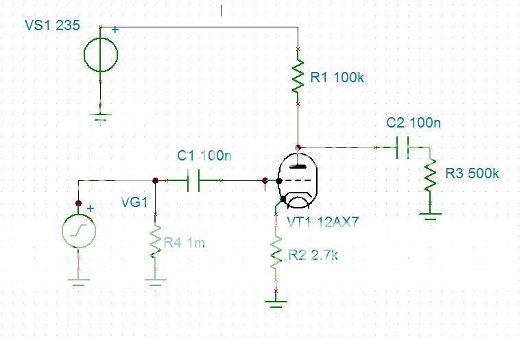
The problem in this case might be you're using the 12AX7 with two grid connections, while it only has one in real life. So connect the output cap between the plate and plate resistor. The output cap also doesn't have a name. It looks like you accidentally filled in a value instead of a name.
Another thing you can try is specifying a start and stop time, instead of letting it run until it has found a steady state. Results will be the same in this case.
Last edited:
I'm a big LTSpice fan. I've simulated loads of tube circuits, from a simple common cathode stage to entire push-pull amplifiers.
The problem in this case might be you're using the 12AX7 with two grid connections, while it only has one in real life.
Another thing you can try is specifying a start and stop time, instead of letting it run until it has found a steady state. Results will be the same in this case.
Thanks! That's already been pointed out. I made a silly mistake with my connections. I appreciate you taking the time to scan over it and see what I was doing wrong. Next time I open LTspice ill try that circuit and macro again and then ill make my connections properly. I'll fix my cap values too.
If you ever feel like sharing the complete tube circuit file that you have I would love to crack it open and poke around in it for learning purposes. Hopefully some time soon after I get this software under control I can get the entire preamp/eq/interstage/push pull output circuit simulated that I have in mind.
Last edited:
Ah, I missed thatThanks! That's already been pointed out. But I appreciate you taking the time to scan over it and see what I was doing wrong.
Hopefully some time soon after I get this software under control I can get the entire preamp/eq/interstage/push pull output circuit simulated that I have in mind.
Did you also try specifying a stop time instead of waiting for a steady state?
A LOT of information from similar efforts has already been shared in the LTSpice User's Group on Yahoo. Use the "Tables of Contents" file in the "Files" section to find messages and files containing work you can borrow from. I think there are simulations of a couple guitar amps, as well as some of the classic hi-fi preamps and power amps, in the group's files.. . . If you ever feel like sharing the complete tube circuit file that you have I would love to crack it open and poke around in it for learning purposes.
Hopefully some time soon after I get this software under control I can get the entire preamp/eq/interstage/push pull output circuit simulated . . .
For a start, there's a whole thread (about 30 pages worth, as I recall) in this Forum's "Tubes/Valves" sub-Forum containing vacuum tube SPICE models, or links to models.. . . now to make an applicable tube library.
I need 6L6's, KT88's.. everybody deserves to be at the party.
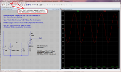
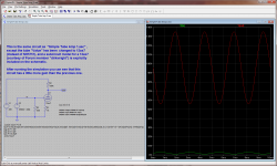
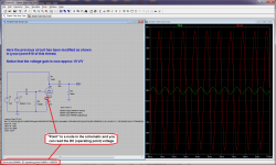
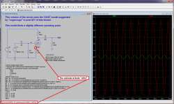
The files I attached to this post illustrate how you could use one of the example files from the LTSpice group as the basis for simulating the simple amp you presented in this thread. It's a step-by-step approach starting with a working simulation of a similar circuit and converting it to YOUR circuit. I have included both screen captures of the working simulations, and the circuit files. Studying the progression may be helpful to you.
Dale
Attachments
okay so im trying to figure out the right way to do this still. I'm using windows 8.1
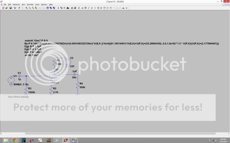
The macro/syntax/directive/code or whatever you want to call it read the following
*
* Generic triode model: 12AX7
* Copyright 2003--2008 by Ayumi Nakabayashi, All rights reserved.
* Version 3.10, Generated on Sat Mar 8 22:41:09 2008
* Plate
* | Grid
* | | Cathode
* | | |
.SUBCKT 12AX7 A G K
BGG GG 0 V=V(G,K)+0.59836683
BM1 M1 0 V=(0.0017172334*(URAMP(V(A,K))+1e-10))^-0.2685074
BM2 M2 0 V=(0.84817287*(URAMP(V(GG)+URAMP(V(A,K))/88.413802)+1e-10))^1.7685074
BP P 0 V=0.001130216*(URAMP(V(GG)+URAMP(V(A,K))/104.24031)+1e-10)^1.5
BIK IK 0 V=U(V(GG))*V(P)+(1-U(V(GG)))*0.00071211506*V(M1)*V(M2)
BIG IG 0 V=0.000565108*URAMP(V(G,K))^1.5*(URAMP(V(G,K))/(URAMP(V(A,K))+URAMP(V(G,K)))*1.2+0.4)
BIAK A K I=URAMP(V(IK,IG)-URAMP(V(IK,IG)-(0.00058141055*URAMP(V(A,K))^1.5)))+1e-10*V(A,K)
BIGK G K I=V(IG)
* CAPS
CGA G A 1.7p
CGK G K 1.6p
CAK A K 0.5p
.ENDS
I was wondering if I had to add all three files to the same folder as the saved drawing since there was a .inc file, .mod, and .csv all beginning with 12AX7. The .csc file for some reason had a thumbnail for a winmovie document.
Is what you see ^ above ^ the way I am supposed to create the models? Or can I just enter the syntax in the spice directive text box and change the name of the tube to match it.
I'm also having trouble with dchisholm's circuit downloads. I did try saving it all in the same folder but I think i'm missing a step somewhere. I get error prompted when I try to start it, ill get the error prompt in a second. AH WAIT I think I figured it out. I didnt have the files out of the zip folder. I relocated them and the sim works!! WOO
- I put only a .inc file for a 12AX7 ( exact name was 12AX7.inc) which currently has a thumbnail for a rich text document in a folder and I saved a new schematic in the same folder. This file was pulled from the pctube_1.11_win.zip download link on the first page of the tube model sticky.
The macro/syntax/directive/code or whatever you want to call it read the following
*
* Generic triode model: 12AX7
* Copyright 2003--2008 by Ayumi Nakabayashi, All rights reserved.
* Version 3.10, Generated on Sat Mar 8 22:41:09 2008
* Plate
* | Grid
* | | Cathode
* | | |
.SUBCKT 12AX7 A G K
BGG GG 0 V=V(G,K)+0.59836683
BM1 M1 0 V=(0.0017172334*(URAMP(V(A,K))+1e-10))^-0.2685074
BM2 M2 0 V=(0.84817287*(URAMP(V(GG)+URAMP(V(A,K))/88.413802)+1e-10))^1.7685074
BP P 0 V=0.001130216*(URAMP(V(GG)+URAMP(V(A,K))/104.24031)+1e-10)^1.5
BIK IK 0 V=U(V(GG))*V(P)+(1-U(V(GG)))*0.00071211506*V(M1)*V(M2)
BIG IG 0 V=0.000565108*URAMP(V(G,K))^1.5*(URAMP(V(G,K))/(URAMP(V(A,K))+URAMP(V(G,K)))*1.2+0.4)
BIAK A K I=URAMP(V(IK,IG)-URAMP(V(IK,IG)-(0.00058141055*URAMP(V(A,K))^1.5)))+1e-10*V(A,K)
BIGK G K I=V(IG)
* CAPS
CGA G A 1.7p
CGK G K 1.6p
CAK A K 0.5p
.ENDS
- I placed a schematic symbol on the drawing for a triode which defaulted to being named triode and it was clearly the correct symbol.
- Then I clicked the spice directive button and entered the file name for the 12AX7 which was/is 12AX7.inc and I also renamed the triode symbol to be 12AX7 by right clicking
I was wondering if I had to add all three files to the same folder as the saved drawing since there was a .inc file, .mod, and .csv all beginning with 12AX7. The .csc file for some reason had a thumbnail for a winmovie document.
Is what you see ^ above ^ the way I am supposed to create the models? Or can I just enter the syntax in the spice directive text box and change the name of the tube to match it.
I'm also having trouble with dchisholm's circuit downloads. I did try saving it all in the same folder but I think i'm missing a step somewhere. I get error prompted when I try to start it, ill get the error prompt in a second. AH WAIT
I think I figured it out. I didnt have the files out of the zip folder. I relocated them and the sim works!! WOO
Last edited:
Okay finally some progress
can someone please point out which library I should download? This syntax seems to work perfectly and I want similar syntax for the rest of my tubes. In the future I'll have to figure out how to sweep the input with different bands of frequencies/noise and how to view the result on the output. I also want to learn how to view THD but im not sure if that's part of the models designs. I need tubes like 12AX7, EL84, EL34, 6L6GC, 6V6GT, KT88, 6CG7, 6FQ7, 12AV7, 1612, 6SJ7.. and more.
Can I use to same syntax on the screen for each tube that is named the same thing?
Last edited:
Looks good! The best place for tube libs is right here on diyaudio in the sticky; Vacuum Tube Spice Models. Another great place is the massive LTSpice Yahoo group. Huge repository.
Once you get the hang of LTSpice, it's actually quite easy to do FFT's and AC response graphs. There are however more complex matters to get it as effective and efficient as possible, but that's not a concern for now.
Once you get the hang of LTSpice, it's actually quite easy to do FFT's and AC response graphs. There are however more complex matters to get it as effective and efficient as possible, but that's not a concern for now.
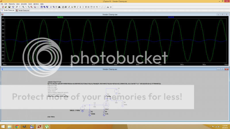
Only just the one file, the .inc file in this case. But if you use Ayumi's models (just the .inc files) you have to change all instances of ^ to ** in LTSpice. To do this you have to place an .INC directive on your schematic and save the .inc file (of the same name) in the same folder as your .asc file, like in this simple tube circuit I've zipped up and attached. You can also do whole libraries this way by using a .LIB directive or an .INC directive. I use a drop-down symbol, but that's another matter for another day.okay so im trying to figure out the right way to do this still. I'm using windows 8.1
I was wondering if I had to add all three files to the same folder as the saved drawing since there was a .inc file, .mod, and .csv all beginning with 12AX7. The .csc file for some reason had a thumbnail for a winmovie document.
Is what you see ^ above ^ the way I am supposed to create the models? Or can I just enter the syntax in the spice directive text box and change the name of the tube to match it.
Attachments
You can use Ayumi Nakabayashi's models (just the .inc files) as long as you change all the instances of ^ to ** in the files. I use notepad++ and notepad2 to do this quickly using the replace function. I'm working on posting a bunch of tube models (mostly triodes) I've traced in Curve Captor and other programs to the sticky.can someone please point out which library I should download? This syntax seems to work perfectly and I want similar syntax for the rest of my tubes. In the future I'll have to figure out how to sweep the input with different bands of frequencies/noise and how to view the result on the output. I also want to learn how to view THD but im not sure if that's part of the models designs. I need tubes like 12AX7, EL84, EL34, 6L6GC, 6V6GT, KT88, 6CG7, 6FQ7, 12AV7, 1612, 6SJ7.. and more.
Can I use to same syntax on the screen for each tube that is named the same thing?
- Status
- This old topic is closed. If you want to reopen this topic, contact a moderator using the "Report Post" button.
- Home
- Amplifiers
- Tubes / Valves
- Tube circuit sim software for free?