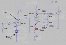
I'm working with 50k load resistors on a cathodyne stage, driving a push pull amp. The B+ is 265v, so I need voltage of B+/5 = say 55v at the cathode.
However, despite trying resistances from 1k through to 10k for the bias resistor, I can't vary the voltage from 78v. I've attached the circuit, and the resistor causing this problem is shown in red.
Is anyone able to suggest how I might be able to reduce the voltage to get maximum swing driving the output tubes?
Attachments
...
Also you may try cheating with a fixed voltage with a simple voltage divider right in the grid of the phase splitter
At about 70V.
also you may try without the 100uf cap
By the way - what is the polarity arrangement of this capacitor. I've got the -ve side facing the 50k resistor, is this correct?
Tom,
The capacitor polarity is right.
Another thought ---
Check you have the 470K grid resistor tied to the right end of the 3K3. It is the grid to cathode voltage which sets tube current and therefore will set the cathode voltage.
If the 470K is tied to the cathode side of the bias resistor by mistake that would account for no change of cathode voltage with the changed bias resistor.
Cheers,
Ian
If the 470K is tied to the cathode side of the bias resistor by mistake that would account for no change of cathode voltage with the changed bias resistor.
Interesting - the stage is behaving as if this is how I have it wired, but I definitely think I have it wired correctly.
Here's a picture - the red dot is the junction of where the 470k (running along the outside of the yellow 0.1uF capacitor) meets the bias resistor (which is underneath the small blue capacitor), and also where the 50k load resistor is soldered.
Does it appear to be wired correctly?
Attachments
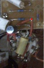
I took out the 100uf capacitor as some have suggested here, and the cathode voltage is still 78v. Something odd though, is that I can't measure the resistance of the bias resistor. I put the multimeter across the 3k3 resistor (tested on both channels with and without the 100uf capacitor in parallel) and there's no resistance at all. What does that suggest?
It suggests that both ends of the resistor are connected to the same circuit node. This also explains your circuit behaviour. Keep checking your wiring and challenging your assumptions until you find the mistake.
Spot on - there was a link on the underside of the tag-strip between the 0.22uF interstage capacitor and the 50k cathode load resistor!
920R bias resistor gets a cathode voltage of 60v. Thanks again to all!
Last edited:
- Status
- This old topic is closed. If you want to reopen this topic, contact a moderator using the "Report Post" button.
- Home
- Amplifiers
- Tubes / Valves
- Troublesome bias resistor, cathodyne stage