Dear forum, I'm deeply sorry for having wasted you time with this. I swear it won't happen again, to my pitiful defense I'm working on this overnight when I'm too tired apparently.
I was using the screens as plates & vice-versa, that's why the low power and problems in general.
sorry guys.

I was using the screens as plates & vice-versa, that's why the low power and problems in general.
sorry guys.
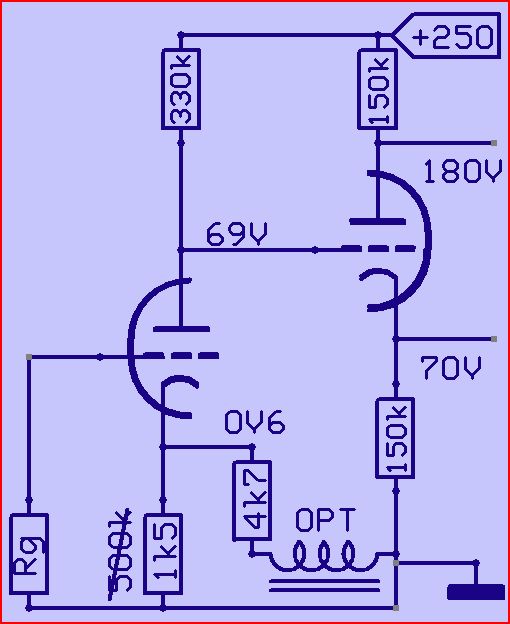
It can work with 1k5 cathode resistor
Look here
Yep!

Clearly the "500k" cathode resistor is a misprint. Maybe it was intended to be "500R" ?
Separating the stages with a coupling cap is something to consider when available B+ is only 250 volts.
Yep!
Something like this, I think.
An externally hosted image should be here but it was not working when we last tested it.
Another thing these old schematics usually lack is grid stops. Cheap and easy insurance against bad surprises. Just add a 1K ohm (or so, whatever you have handy) resistor in series with each grid, mounted right at the valve socket pin. For pentodes, use one on the G2 also.
All good fortune,
Chris
All good fortune,
Chris
I noticed a 12ax7 with 100k anode resistor at +300V
with 250V, shouldn't anode resistor be smaller
used to be a 150k anode and cathode, at 250v , I replaced both with 66k , but eventually I've found a bigger problem, very stupid indeed, I only left the thing running for seconds each time I took measures and tested things, so hopefully output tubes are not completely damaged.
Yep!
Clearly the "500k" cathode resistor is a misprint. Maybe it was intended to be "500R" ?
I will try that too and share the results. The circuit is in a book form the '60s, there aren't that many schematics around for EL90 as opposed to EL84 obviously.
I only left the thing running for seconds each time I took measures and tested things, so hopefully output tubes are not completely damaged.
You have not hurt them at all. Anode (plate) voltage was applied and at least as large as G2 voltage? No harm, no foul.
All good fortune,
Chris
Ok so this is what I did and bang! now there's plenty of output power, although there's excellent bass response, I mean very deep "kicks" and no so much top end, anyway it's just a matter of tuning the baxandall tone controls I think.
I have already built the second channel to make it stereo.
Thank you Mona (you were right) DF96, Cris & directdriver and all the forum.
I will continue to improve it step by step.
I have already built the second channel to make it stereo.
An externally hosted image should be here but it was not working when we last tested it.
Thank you Mona (you were right) DF96, Cris & directdriver and all the forum.
I will continue to improve it step by step.
An externally hosted image should be here but it was not working when we last tested it.
If it's ever rebuilt or much rewired, you may want to consider changing the pins 6, 7, 8 triode to the first stage and the pins 1, 2, 3 to the second. This would allow you to use the type 12DW7/ 7247 valve which is famous in this service. Its pins 1, 2, 3 triode is 1/2 of a type 12AU7/ ECC82 and lets you run even more current here, maybe 3 or 4 milliAmps.
Nothing to lose sleep over, but maybe worthwhile as your amp progresses.
All good fortune,
Chris
Nothing to lose sleep over, but maybe worthwhile as your amp progresses.
All good fortune,
Chris
Ok so this is what I did and bang! now there's plenty of output power, although there's excellent bass response, I mean very deep "kicks" and no so much top end, anyway it's just a matter of tuning the baxandall tone controls I think.
When decoupling the PS with biggish electrolytics you might experience 'singing' of bass notes if the PS is marginally stable. Depending on topology, PSRR and stability margin this effect might deminish when caps are settling, lowering the PS impedance in case the caps were not freshly formatted. Black Gate is known for this property.
A quick fix for the HF might be bypassing that electrolytic with a small (1%) foil cap to see if things clean up.
Last edited:
- Status
- This old topic is closed. If you want to reopen this topic, contact a moderator using the "Report Post" button.
- Home
- Amplifiers
- Tubes / Valves
- Help 6AQ5 pushpull