I built this circuit using the "super" 6BG6GAs. Works and sounds great although I have to modify the fixed bias circuit to increase the voltage. I'm only able to get -30V now.
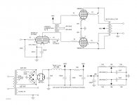
I read in another thread that when simulating the 6BY5G in PSUD2, to use the 5V4 model. I did that although there is not really a way that I know of to simulate the hybrid bridge configuration that I used. I simulated using full wave with a center tapped xfmr. The simulation showed 450V for the power tube B+ at -45V fixed bias for about 50mA/tube.
The B+ ended up being 380V, and I'm able to bias the tubes to 60mA. I'm sure the voltage will come up some when I get the fixed bias voltage up, and can bias the tubes a little colder, but probably not to 450V. I could also change the 62R series resistors to 50R safely which may help a little.
Has anyone successfully simulated a 6BY5 hybrid bridge in PSUD2?
Attachments
^^
I don't use that PSUD thingie to design power supplies. I use a scientific calculator and the plate characteristics. Over at Frank's, the spec sheet for this type is very sparse, and doesn't include any plate characteristics. Given that you're using a plate bias of 50mA, I wouldn't have considered the 6BY5 in the first place. The Isurge= 525mA is pretty anemic, and places a severe limit on the size of the reservoir capacitor. That will make for lots of ripple, and cut the output voltage way down. If I felt I had to hollow state the PS, I'd rather go with a 5U4GB or a 5BC3 (like a 5U4, but in the large, nine pin format) that have a stiffer Isurge= 1.0A/plate.
Still, given the difference between what was predicted and what you measure (70V) that looks to be in line with the expected forward loss across a hollow state diode.
Thanks for the reply.
Separate 6BY5s are used for each channel. Only 2 power tubes + the driver for each channel. 6BY5 is good for 175mA and the circuit is drawing 116mA/6BY5. No 5V winding on my PT. I suppose I could convert to a SS FWB instead.
Vacuum tube rectifiers don't all have the same voltage drop, but I could not find a definitive answer on the 6BY5.
Last edited:
Hi!
The Tung-Sol data sheet quotes 32V at 175mA. In your application you maybe have 20V drop. A 5U4 would have a much larger drop compared to the 6BY5
Thomas
Vacuum tube rectifiers don't all have the same voltage drop, but I could not find a definitive answer on the 6BY5.
The Tung-Sol data sheet quotes 32V at 175mA. In your application you maybe have 20V drop. A 5U4 would have a much larger drop compared to the 6BY5
Thomas
Hi Scott,
I use choke input supplies which do not impose severe peak currents to the rectifier.
It is important to keep the currents within the rated limits. With moderately sized input caps the winding resistance of the power transformers is usually enough.
Best regards
Thomas
I use choke input supplies which do not impose severe peak currents to the rectifier.
It is important to keep the currents within the rated limits. With moderately sized input caps the winding resistance of the power transformers is usually enough.
Best regards
Thomas
bias supply mod
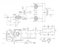
I used a 5W 8-115VAC xfmr wired in reverse to the heater winding and changed to a FWB to feed the bias supply. This brought my raw bias voltage up to -80V, allowing greater bias range, and the output tubes are now biased at 49mA.
The B+ came up to 425V. I thought my SE KT88 sounded great, but this is the tightest sounding amp I have ever built. The interstage xfmrs are quite pricey, but well worth it.
Scott
Attachments
Hi Scott,
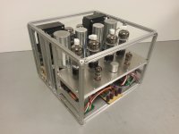
I know this thread is old, but I must say that I am very impressed by your build. What is the name of that aluminum and where did you get it?
Also, I stumbled upon this project following the 12W6pse. I was wondering, do you have a favorite amp you've made so far?
Thanks for sharing your work. Best wishes.
The aluminum is from MicroRax.
Hard to say which amp is my favorite. With my Altec 604 speakers I like the KT88SE, 12W6PSE or 2A3SE for jazz or classical music. For hard rock music or music like Pink Floyd I like the 6CA7 or 6BG6 push pull amps. Although I rotate all of them in and out service periodically.
All the best.
Hard to say which amp is my favorite. With my Altec 604 speakers I like the KT88SE, 12W6PSE or 2A3SE for jazz or classical music. For hard rock music or music like Pink Floyd I like the 6CA7 or 6BG6 push pull amps. Although I rotate all of them in and out service periodically.
All the best.
- Status
- This old topic is closed. If you want to reopen this topic, contact a moderator using the "Report Post" button.
- Home
- Amplifiers
- Tubes / Valves
- IT coupled 6BG6GA