I'm currently experimenting with frequency responses and have a few different scenarios I'm interested in testing.
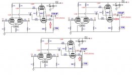
Is anyone able to advise what changes in distortion and/or frequency response we might reasonable expect to hear when we make the following changes to the circuit (see the red arrows in attached picture):
The first circuit (top left) shows the design as laid out by John Broskie, and I calculate the frequency response to be:
100k in parallel with 10k, in parallel with 600R (headphone impedance) = 562.85.
With a 150uF electrolytic cap, -3dB response is:
159155/150/562.85 = 1.885Hz
Attachments
")
Wow, a bi grid valve!
Grids don't sink current, so the 100k is not in parallel with the 600/10k.
In the diagram top left the grid is a virtual earth, so the 100k is effectively in parallel, so lordearl's calculation is correct. Not that the 100k makes any difference compared with 600R.
In the last two circuits you have removed the local feedback from the lower output triode, so it will start clipping way sooner than the upper triode. More distortion is inevitable.
Last edited:
Is the amplification high enough to actually pass for a virtual earth?
Very good point as this stage is merely a unity gain buffer (the initial stage has about 36dB of gain).
Thoughts anyone?
Very good point as this stage is merely a unity gain buffer (the initial stage has about 36dB of gain).
Thoughts anyone?
Doesn't really matter as it is swamped by the 600 ohms of the phones.
Cheers
Ian
Doesn't really matter as it is swamped by the 600 ohms of the phones.
Cheers
Ian
Sorry - do you mean this is a good or bad thing? If the latter, how can we optimise the circuit?
Sorry - do you mean this is a good or bad thing? If the latter, how can we optimise the circuit?
What I meant to say is thet the 100K and 10K resistors do not matter because they are swamped by the 600 ohms of the headphones.
When you say 'optimise' the circuit, what do you mean?
Cheers
Ian
Ok I follow you now.
Yes unfortunately being a 'linestage' it's not technically able to generate enough current to drive headphones - hence I'm querying whether it is possible to further modify the topology (besides just changing the capacitor and a single resistor) to suit driving headphones.
Yes unfortunately being a 'linestage' it's not technically able to generate enough current to drive headphones - hence I'm querying whether it is possible to further modify the topology (besides just changing the capacitor and a single resistor) to suit driving headphones.
Ok I follow you now.
Yes unfortunately being a 'linestage' it's not technically able to generate enough current to drive headphones - hence I'm querying whether it is possible to further modify the topology (besides just changing the capacitor and a single resistor) to suit driving headphones.
The output stage is essentially an SRPP with 100% NFB - it's just configured differentially. The bottom line is the small signal output impedance is determined by the tube gm and the output drive capability is determined by the standing current. If you want it to be better able to drive a 600 ohm load you need to increase both. What tube are you using?
Cheers
Ian
I'm using the 6N23P-EV on the output.
The good news is that there are jumpers to switch between 12v/6v filaments so nearly any nine pin bottle will work. Which tube do you recommend?
Difficult to say. It depends on the headphones you want to drive and to what level you want to drive them. What is the specification of the headphones, in particular their sensitivity?
Cheers
Ian
Thanks Ian - they're Beyerdynamics DT880, 600 ohms impedance, sensitivity is 96dB.
OK. That 96dB SPL has no specified test conditions so we do not know if it is for 1mW or 1V input. As its 600 ohms lets assume it is 1mW or 0.775V. As a rule, to allow for peaks to be handled properly I would set the maximum SPL at 117dB which is just over 20dB higher than the 96dB sensitivity so we need to be able to output as much as about 8V rms into a 600 ohm load. That means the stage needs to be able to output a current of 8/0.6 mA rms = 13.3mA rms = 18.85mA peak. So we need to set the standing current to about this value so let's call it 20mA for a bit of safety margin. On this basis I would suggest you try an ECC99 with a 300 ohm cathode resistor in the SRPP stage.
Cheers
Ian
Ok great - thanks. Well I have 300R resistors, so that's under control. However, I don't have any ECC99. I do have a pair of E288CC, would that do the trick?
The E88CC is just an SQ version of the ECC88 and the 6N23P but is specified at a higher grid plate current where it has a lower plate resistance, Difficult to say whether in practice it will perform any better than a 6N23P at 20mA. Running it at 20mA means you need to be careful not to exceed its plate dissipation so I would limit the HT supply to 200V. I would recommend you start with 56 ohm cathode resistors and keep an eye on the plates to make sure they do not start to glow red.
Cheers
Ian
Cheers Ian, although the E288CC seems to be more similar to the ECC99?
pdf datasheet E288CC datenblatt | High Fidelity Tubes
(The ecc88/6922 family looks to be quite different)
I can't tell from the datasheet what we would need to do to run the E288CC at 20mA.
pdf datasheet E288CC datenblatt | High Fidelity Tubes
(The ecc88/6922 family looks to be quite different)
I can't tell from the datasheet what we would need to do to run the E288CC at 20mA.
Cheers Ian, although the E288CC seems to be more similar to the ECC99?
pdf datasheet E288CC datenblatt | High Fidelity Tubes
(The ecc88/6922 family looks to be quite different)
I can't tell from the datasheet what we would need to do to run the E288CC at 20mA.
You are correct. I was confusing it with the E188CC.
Looking at the Philips E288CC datasheet, with 100V plate voltage and 20 mA plate current you need about 1.5V bias. This means the cathode resistor needs to be about 1500/20 ohms = 75 ohms.
Cheers
Ian
Looking at the Philips E288CC datasheet, with 100V plate voltage and 20 mA plate current you need about 1.5V bias. This means the cathode resistor needs to be about 1500/20 ohms = 75 ohms.
Ok just installed the 75R resistors and these are the measurements for the two E288CC;
Tube 1:
Pins 1,3 = 83.3v
Pins 6,8 = 108.3v
Voltage across the cathode resistors: 2.4v
Tube 2:
Pins 1,3 = 81.4v
Pins 6,8 = 110.2v
Voltage across the cathode resistors: 2.4v
B+ is 276v, with 196v measured from pin 1 of each tube to GND.
Seems a little different from the datasheet.
How do we calculate the current?
Just so as we are absolutely clear can you post the scematic of what you have measured?
Cheers
Ian
- Status
- This old topic is closed. If you want to reopen this topic, contact a moderator using the "Report Post" button.
- Home
- Amplifiers
- Tubes / Valves
- Grid resistors -> GND