Hey Guys,
I hope everyone had a wonderful New Year's, and I wish a productive year ahead to all!
I wanted to sumarize what I have in mind, and get some feedback while I am drawing up schematics....
True Dual Mono PS.
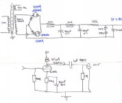
Tube hybrid rectifier with 2 12AX4GTB- 20H-40uF-20H-40uF regulated with OA2.
LM317T regulated fillaments.
Pimm BMMCCS loaded 12B4A (as per Brett's previous posts), not exactly sure yet of opperating points??? Parafeed output.
Dact stepped attenuator?
Seperate chassis for PS and Audio circuit.
Cosmetics TBD, but nice of course")
I am going to draw by hand some schematics and post within a few days for review. On that subject, does a simple schematic drawing program exist which is user-friendly?
Any comments/concerns before I move ahead are greatly appreciated?
Thanks All,
Bryan
I hope everyone had a wonderful New Year's, and I wish a productive year ahead to all!
I wanted to sumarize what I have in mind, and get some feedback while I am drawing up schematics....
True Dual Mono PS.
Tube hybrid rectifier with 2 12AX4GTB- 20H-40uF-20H-40uF regulated with OA2.
LM317T regulated fillaments.
Pimm BMMCCS loaded 12B4A (as per Brett's previous posts), not exactly sure yet of opperating points??? Parafeed output.
Dact stepped attenuator?
Seperate chassis for PS and Audio circuit.
Cosmetics TBD, but nice of course
I am going to draw by hand some schematics and post within a few days for review. On that subject, does a simple schematic drawing program exist which is user-friendly?
Any comments/concerns before I move ahead are greatly appreciated?
Thanks All,
Bryan
Well, you'll have a highish output impedance (though not disastrously so). I don't have my tube handbook to hand, but I'd guess 7-10Kohm? Also, you could simplify that power supply a LOT, since a good CCS will increase PS rejection.
I guess what I can't get my head wrapped around is why you'd use a 12B4 in this application in the first place. You don't need a lot of current, which is what that tube is made for. I'll admit, though, that the more logical choices are pretty prosaic...
I guess what I can't get my head wrapped around is why you'd use a 12B4 in this application in the first place. You don't need a lot of current, which is what that tube is made for. I'll admit, though, that the more logical choices are pretty prosaic...
Hey SY,
You think the PS should or could be simplified...?
One of my goals for this project is to push my abilities, with the use of new topologies, hence the voltage regulation, and the CCS loading. Given that, does the circuit look sound?
Some of my specific questions are:
1. What is a good capacitance to have directly after the VR tubes. What type of cap would be best in this position, PIO?
2. With the opperating points I have chosen, do I really need 180 volts from the PS, or could I get by with an 0A2 and leave it at 150 ish? I kinda like the idea of having the extra voltage should I chose to tweak the points while on the breadboard.
For the heater supply, I am thinking of a simple CRCRC LT317 regulated 12.6 volt. Thoughts.
I am working on/with the advice of others, who have helped me significantly. I am learning lots, which was another main goal of this project
I'm a pretty strong believer in the efficacy of caps for decoupling. This is a class A stage, so you're not going to need particularly stiff, tightly-regulated rails. And the CCS improves PS rejection. You just need the rail not to bounce around.
If it were my own unit, I'd either drop the VR part entirely and take DC off the big cap or, if I really wanted objectively tighter regulation, low Z, and low noise, use a solid state regulator circuit. This is DC we're talking about.
You'll gain some linearity, at the cost of higher source Z if you get rid of the cathode cap. At the sort of voltages that are realistic for a line stage, like 1-2V, sufficient linearity for audible transparency is pretty easy, but chasing the distortion numbers down can be an interesting and educational exercise.
And do make sure that you either have some sort of output muting on warm-up or that the following device will require warm-up, too.
Hi,
That's how it should be done indeed; 0.047µF to 0.100µF maximum per VR.
Bryan, your PS looks OK.
Just don't forget to ground the negative of the PS after the rectifier.
Probably just an oversight on the drawing but I thought I'd mention it just in case.
Cheers,
Having said that, I'd be inclined to bypass each seperately, for the sake of RF stability.
That's how it should be done indeed; 0.047µF to 0.100µF maximum per VR.
Bryan, your PS looks OK.
Just don't forget to ground the negative of the PS after the rectifier.
Probably just an oversight on the drawing but I thought I'd mention it just in case.
Cheers,
How about putting a battery under the cathode instead of the R||C pair? You'll get the required bias voltage, and an AC path to ground that has lower DCR than an electrolytic capacitor (or so I read, someone's posted the numbers somewhere). Hook up the battery with the + terminal connected to the cathode and the - terminal connected to ground, replacing the resistor and capacitor.
That's what I did with the driver stage of my amp, and I like the sound better this way than with the resistor/cap pair. I only needed 4V @ 22mA though, you need 12V @ 35mA. Radio Shack sells some NiMH cordless phone batteries that were perfect for my application (both the voltage and the current ratings were what I needed), you might have to look around for batteries or stack 2-3 to get the voltages you need. For instance, I think RS has 3.6V batteries (close to 4V when fully charged) that can safely handle a 35mA current through them, stacking 3 of those should get you the 12V you need. FWIW, I have a CCS load up on top too.
The one concern I've read of with batteries is related to non-linear impedance with frequency, but not everyone agreed on whether that was true. And I found other people who've run similar setups for extended durations, so I was pretty comfortable about the safety side of things.
Anyway, since you said you wanted to play with new ideas/topologies, I thought I'd throw that out there as an option. This is if you plan on keeping the cap, of course. Removing the cap and leaving only the resistor (like SY suggested) would be the other direction to go in. If I were you, I would try both.
Hi Bryan
Your circuit certainly looks good and will very probably also sound good as well. If it doesn't you can always replace the CCS with a nice plate choke
Please explain your design decision re the hybrid rectifier. Is it supposed to sound better than just tubes alone?
Your circuit certainly looks good and will very probably also sound good as well. If it doesn't you can always replace the CCS with a nice plate choke
Please explain your design decision re the hybrid rectifier. Is it supposed to sound better than just tubes alone?
Hi,
Peter,
The diode tube can be bypased by silicon diodes to increase the voltage and power handling of the bridge.
In this arrangement the diode tube passes very little forward current.
But the tube still sets the tone of the rectifier by the way it handles the shut of current when it is reverse biased.
You will still get the valve sound without the harshness of the silicon diode cutoff in reverse bias.
The silicon diode on its own can sound like a door slamming but the diode tube softens the rectifier.
Note also that this arrangement allows the use of a FWB configuration without a CT on the powerxformer and the silicon diodes don't require heaters.
Cheers,
Hi,
Wouldn't dare...Would I?
Time for Gary Pimm's little pic:
Cheers,
I expect you wanted to stir up some controversy Frank ?
Wouldn't dare...Would I?
Time for Gary Pimm's little pic:
Cheers,
Attachments
hi all
yes, the 12b4 is such a cooooool tube. i built one too. revised the grid stopper from 220ohm to 1kohm recently.
it's very transparent. almost "disappears".
http://www.diyparadise.com/etude.html
donjuan
yes, the 12b4 is such a cooooool tube. i built one too. revised the grid stopper from 220ohm to 1kohm recently.
it's very transparent. almost "disappears".
http://www.diyparadise.com/etude.html
donjuan
fdegrove said:Hi,
Wouldn't dare...Would I?
Time for Gary Pimm's little pic:
Cheers,
But he's already got the full-wave version.
You said "bypassed". To me that mean "shunt" or parallel.

Hi,
And I meant what I said...
Cheers,
You said "bypassed". To me that mean "shunt" or parallel.
And I meant what I said...
Cheers,
Attachments
Hi,
Peter, John,
Should have directed you here first:
HYBRID RECTIFIER
I recall Gary Pimm contributing in a thread where this was discussed here but I'ven't found it yet.
Cheers,
Peter, John,
Should have directed you here first:
HYBRID RECTIFIER
I recall Gary Pimm contributing in a thread where this was discussed here but I'ven't found it yet.
Cheers,
Hi Guys,
Good! Anything else you think could be improved?
Yup, an oversight on the drawing.
What type of cap is best in this application?
I've thought about battery bias, something I may try along the way. Also, would it be possible to bias with LED's, or is this a waste of time?
I would appreciate some feedback on output transformers. Any suggestions and reasoning?
I have to give credit to Brett for the circuit! Thanks.
Finally, I am correct in assuming the damper diodes will give me a slow start up?
Thanks,
Bryan
Bryan, your PS looks OK.
Good! Anything else you think could be improved?
Just don't forget to ground the negative of the PS after the rectifier.
Yup, an oversight on the drawing.
That's how it should be done indeed; 0.047µF to 0.100µF maximum per VR.
What type of cap is best in this application?
I've thought about battery bias, something I may try along the way. Also, would it be possible to bias with LED's, or is this a waste of time?
I would appreciate some feedback on output transformers. Any suggestions and reasoning?
I have to give credit to Brett for the circuit! Thanks.
Finally, I am correct in assuming the damper diodes will give me a slow start up?
Thanks,
Bryan
Hi,
Usually I don't use any at all but that's because I select the VR tubes.
If you want to put a cap I'd use a quality MKP type but I guess a MKT or MKC would do just the same.
That should be possible, no idea what that would sound like though.
For use with this preamp iso the coupling cap?
Yes.
Cheers,
What type of cap is best in this application?
Usually I don't use any at all but that's because I select the VR tubes.
If you want to put a cap I'd use a quality MKP type but I guess a MKT or MKC would do just the same.
Also, would it be possible to bias with LED's, or is this a waste of time?
That should be possible, no idea what that would sound like though.
I would appreciate some feedback on output transformers. Any suggestions and reasoning?
For use with this preamp iso the coupling cap?
Finally, I am correct in assuming the damper diodes will give me a slow start up?
Yes.
Cheers,
- Status
- This old topic is closed. If you want to reopen this topic, contact a moderator using the "Report Post" button.
- Home
- Amplifiers
- Tubes / Valves
- 12B4A Linestage