I've been reading some discussion about using DC and/or regulated heater supplies. Using DC for heaters is tricky because normal 6.3VAC transformers sometimes won't work.
I have attached a schematic below and indicate what transformer voltage is required.
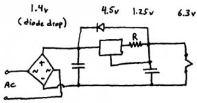
The heater uses 6.3V, but this schematic features current regulation. For example, assume the tube heater requires 420mA.
The voltage regulator maintains 1.25V across R. Therefore, to get 420mA over a 1.25V drop, 1.25/0.420 = 3 Ohms.
The voltage regulator also drops voltage. Depending on which type you choose, this can be from 3 to 4.5V. The LM317 is on the high end. LT1083/84/85/86 may be a bit lower. I'll contact Linear Technology for exact numbers. If you don't allow enough voltage to cross the regulator, it will stop working.
The diode bridge also drops voltage. A normal diode at full load will drop 0.7V. Since the power goes through 2 diodes, expect 1.4V to be lost.
Add these voltages: 6.3 (heater) + 1.25 (resistor) + 4.5 (regulator) + 1.4 (diodes) = 13.45.
In the end, the circuit requires about 13.45VAC peak-to-peak, therefore about 9.5VAC rms. Hammond makes some 10V 1A transformers (164G10) for $11 from Digikey that could power two of these tubes. Each tube needs its own current regulator, otherwise, one tube could be slammed with too much current!
The diode pictured is for reverse-potential protection. The capacitors could be anything, but I'd recommend at least a 6800uF can on the input.
The resistor will dissipate 0.5W and the regulator will dissipate 1.9W. Heatsink appropriately!
I have attached a schematic below and indicate what transformer voltage is required.
The heater uses 6.3V, but this schematic features current regulation. For example, assume the tube heater requires 420mA.
The voltage regulator maintains 1.25V across R. Therefore, to get 420mA over a 1.25V drop, 1.25/0.420 = 3 Ohms.
The voltage regulator also drops voltage. Depending on which type you choose, this can be from 3 to 4.5V. The LM317 is on the high end. LT1083/84/85/86 may be a bit lower. I'll contact Linear Technology for exact numbers. If you don't allow enough voltage to cross the regulator, it will stop working.
The diode bridge also drops voltage. A normal diode at full load will drop 0.7V. Since the power goes through 2 diodes, expect 1.4V to be lost.
Add these voltages: 6.3 (heater) + 1.25 (resistor) + 4.5 (regulator) + 1.4 (diodes) = 13.45.
In the end, the circuit requires about 13.45VAC peak-to-peak, therefore about 9.5VAC rms. Hammond makes some 10V 1A transformers (164G10) for $11 from Digikey that could power two of these tubes. Each tube needs its own current regulator, otherwise, one tube could be slammed with too much current!
The diode pictured is for reverse-potential protection. The capacitors could be anything, but I'd recommend at least a 6800uF can on the input.
The resistor will dissipate 0.5W and the regulator will dissipate 1.9W. Heatsink appropriately!
Attachments
I built this for my 2A3 amp, with Hammond 6.3V transformers, individually heatsinked (heatsunk?) MBR735 high current Schottky diodes and an LT1085. It sounded pretty good, but got really hot under my already crowded chassis, so I eventually went back to AC filaments. As you pointed out, using higher voltage transformers will allow you to produce higher regulated voltages (that's a pretty redundant statement ") )
)
If you're planning for this from the start and take care of ventilation, this can work well. I have almost all of the parts lying around for a 2.5V/2.5A current regulated supply, in case anyone's interested (shameless plug)
http://www.diyaudio.com/forums/showthread.php?s=&threadid=21409
)If you're planning for this from the start and take care of ventilation, this can work well. I have almost all of the parts lying around for a 2.5V/2.5A current regulated supply, in case anyone's interested (shameless plug
)http://www.diyaudio.com/forums/showthread.php?s=&threadid=21409
Hi,
You don't expect anyone to actually think or, do you???
...You don't....I know..........
Oh well....Maybe one day.....
BTW. You have shown that current regulated supplies only make sense with a series string of valves requiring a total voltage of more than 6.3V...
You don't expect anyone to actually think or, do you???
...You don't....I know..........
Oh well....Maybe one day.....
Hi,
Good...I'm not alone anymore then...
I provoked thought in the DIY Turntable thread and almost got banned for life, how hard is it to think for oneself?
Is it Mc Donalds, Coke, Pepsi or what?...
Were'all just sheep in a heard, aren't we?
Cheers,
Actually, I do! And if not, I hope to provoke thought (although I always prefer to think it was going to happen anyway).
Good...I'm not alone anymore then...
I provoked thought in the DIY Turntable thread and almost got banned for life, how hard is it to think for oneself?
Is it Mc Donalds, Coke, Pepsi or what?...
Were'all just sheep in a heard, aren't we?
Cheers,
The circuit pictured, EC8010, is a 420mA current regulator capable of delivering regulated output up to about 6.5VDC. It is appropriate for a single tube heater. This circuit will control the current while the heater is cold, thereby eliminating the turn-on surge.
If the voltage of this circuit is increased, multiple heaters could run in series. This circuit is not appropriate for heaters in parallel.
Other currents can be obtained by varying the value of R.
The purpose of this example was to illustrate that running heaters with DC or regulated DC may not always be as straightforward as placing a diode bridge onto an ordinary filament transformer.
- Status
- This old topic is closed. If you want to reopen this topic, contact a moderator using the "Report Post" button.
- Home
- Amplifiers
- Tubes / Valves
- Regulated Heater Supply