Here's my first go at a low powered SET amp.
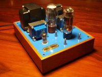
6AS7 power stage, 12AX7 driver stage, 5V4G rectifier, 15W Edcor GXSE (1.7K) output transformers, Hammond (270FX) power transformer, Auricap signal capacitors, 24-step attenuator on the front end, Hammond chassis.. I would say this was somewhat of a budget build, but I'm very very happy with the sound. About 3W output power per channel.
The wiring isn't overly pretty (I've since tidied a few things up), but the amp is dead quiet at full volume, even with my ear directly next to the drivers I'm using (Fostex 206e).
Last edited:
Congratulation, thejoi!
But I have in my head some questions.....6AS7 is tube with low works +U = about 150-180 v. Why You use PT with 550 v? To receive 150-160 v You use 1 kohm in PS /this is not good choice/, and up cathode U to 77 v, that need pre stage with big mu, big +U, that lead to not very good choice of 12AX7 /IMO, sorry/ for sounding. And 24 step attenuator is good choice, but it's nominal, IMO is not suitable, because if it middle point is in low volume, upper part will be big resistance for small MF and HF signals.
6AS7 is great tube and deserves very good 25 Wt OT.
Your schematic is right, Your built is very nice...but it is like....fly from New York to Chicago via San Diego....Sorry for my notices and bad English.
Last edited:
Congratulation, thejoi!
But I have in my head some questions.....6AS7 is tube with low works +U = about 150-180 v. Why You use PT with 550 v? To receive 150-160 v You use 1 kohm in PS /this is not good choice/, and up cathode U to 77 v, that need pre stage with big mu, big +U, that lead to not very good choice of 12AX7 /IMO, sorry/ for sounding. And 24 step attenuator is good choice, but it's nominal, IMO is not suitable, because if it middle point is in low volume, upper part will be big resistance for small MF and HF signals.
6AS7 is great tube and deserves very good 25 Wt OT.
Your schematic is right, Your built is very nice...but it is like....fly from New York to Chicago via San Diego....Sorry for my notices and bad English.
Thanks. Haven't we had this conversation before though?

I am using the 6AS7 with 170V from plate to cathode.. 245V on plate, 75V on cathode = 170V plate to cathode.
As for that 1Kohm resistor you're seeing, it's not in the main power supply string, it is used for the leg that feeds B+ to the driver. It has nothing to do with the B+ that the 6AS7 sees.
If you'll notice, there is indeed a 250 ohm resistor between the chokes (after the leg that feeds the driver) which does drop my B+ for the 6AS7 by about 37.5V (150mA * 250ohm). I suppose I could have used a 500VCT power transformer, but then I'd probably be a bit on the low side. That is why I used a 550VCT power transformer.. Between the voltage drops through the rectifier, chokes, and output transformer, I arrive at pretty much exactly the B+ I want for this amp.
As for the fact that my 6AS7 cathode voltage is 75V, requiring a large swing, the 12ax7 is absolutely fine for this task. I've asked you before why you think the 12ax7 isn't a good choice for a driver, and all you've really told me is that you feel as though it's harsh sounding and for use in guitar amps.. As I've mentioned before this sound that you're describing is likely because of how the 12ax7 has been configured in the circuit's you've used it in. Very often the 12ax7 gets set up with too small a load, or bias resistor, and then you get grid conduction. An incorrect bias and small load makes it sound "harsh".
With the bias point and load as it is in this circuit, it provides the swing required, and honestly sounds really really good IMO.
I did not design this circuit, and the person who did provided a plot for the driver as it's configured in this circuit (Which I'm attaching to this post).

His explanation of the 12ax7 as it's configured is:
On this plot, the blue line is the dc load line and the red line is the ac load line drawn through the static operating point.The green vertical lines represent the +/-75v excursions from the static operating plate voltage. You should be able to see that the excessive input swing will take the stage into compression before it starts to clip. But in either case, the swing into the power stage will exceed the power stage bias first which means the the driver will remain stable and well behaved right up to the point where you have maxed out the power stage. I think this is a good solution. If more people would simply plot the load lines for their drivers, there would be a lot less consternation over final amplifier performance.
As for the selection of output transformer, I chose this 15W Edcor because it can easily handle the current required, and I've seen a number of tests showing that it has very good frequency response.
I also found this article very interesting on the subject of audio bandwidth, and some test data from various output transformers. Something that stuck out to me from this article is primary inductance, and that the larger the primary inductance of the output transformer, the slower the transient response will be.
Here's a quote from the article on that subject
Sometimes you’ll hear an amplifier described as “light” or “responsive”. This is an amplifier that has good transient response. One that can rapidly change levels without undue lags or distortions. On the other end of the spectrum an amp may be described as “slow”, “dull”, or “muddy”. These are examples of an amplifier which has poor transient response. It is one that sounds fine with music that is melodious, which ebbs and flows easily, but cannot handle the rapid changes that a dynamic score requires.
The 25W SE Output transformers in my price range had much higher primary inductance, and just really seemed like overkill.
The GXSE-15 Output transformers have great frequency response, a low primary inductance, and they can easily handle the current I'm throwing at them. Again, from my experience listening to this amp, it sounds great to me. Very clear full range of frequencies, and it does not sound slow or muddy. It's very very pleasing to my ears.
I would be interested in hearing or seeing some data on the subject of why you believe the 12ax7 is a poor choice for this amp, or why the 15W Edcor output transformers are a poor choice.
To each their own I suppose. I know you like the 6AS7 with fixed bias, and in an OTL configuration. Maybe some day I will try that.
1 kohm or 250 ohm...this is the same for decrease +U, that is not good step. And 77v on cathode resistor is not good choice and with cathode cap /6AS7 works amazing with fixed bias, without "parasite " cathode res. and cap, that color the sound.../.....
And if You try pre tube ECC88, E80CC, 12AT,U7, 6SN7/of course with low AC PT- 2 X 150v/.... I don't doubt You will sense the difference...
/When I made my first tube ampl, I though that this is the top of the ace cream..../
Your modes in Your schematic are right, but Your way to "big" sound, IMO isn't direct....sorry.
Last edited:
1 kohm or 250 ohm...this is the same for decrease +U, that is not good step. And 77v on cathode resistor is not good choice and with cathode cap /6AS7 works amazing with fixed bias, without "parasite " cathode res. and cap, that color the sound.../.....
And if You try pre tube ECC88, E80CC, 12AT,U7, 6SN7/of course with low AC PT- 2 X 150v/.... I don't doubt You will sense the difference...
/When I made my first tube ampl, I though that this is the top of the ace cream..../
Your modes in Your schematic are right, but Your way to "big" sound, IMO isn't direct....sorry.
I was within 30-ish volts of my desired B+.. I wouldn't say that's a huge margin of error. If I had used a 500VCT power transformer I think I would have been struggling to get high enough B+ (especially for my driver - notice that the 250ohm resistor is after the feed to the driver power supply node). I'd be surprised if that 250 ohm resistor does much to color the sound. Why do you say it's not a good step?
I also still don't really gather why you don't like the cathode bias design of the 6AS7 with cathode bypass. Cathode biasing seems to be very popular with many many SET amps that I've come across.
I also still don't know why you dislike the 12ax7 so much as a driver, you haven't really backed that up with anything. There's nothing harsh sounding about this amp.
Last edited:
Cathode resistor 1 kohm, depending of it structure /not 250 ohm in PS/ with cathode cap, that is worst, also depending of it structure, will color the sound.
Cathode bias is good, why don't use fixed, if it's better for real sound?
{In Your place, I will use PT with AC about 150, 160 v and will use fixed bias for output stage with 1 or 2 passive elements on grid /note, please, every element colors/ , for real sound}
I noted all that and I'd like to advice You to go to direct way to real sound.../Hi-end is back proportional to the number of composite parts....my moto....and I'm sure/.
About OTL....Amp. with OT is good, OTL with output C maybe is better, but OTL-OCL is the best, IMO.
OT is "Parasite" element. IMO.
Please, don't doubt, I'm not bad man...
Last edited:
Cathode resistor 1 kohm, depending of it structure /not 250 ohm in PS/ with cathode cap, that is worst, also depending of it structure, will color the sound.
Cathode bias is good, why don't use fixed, if it's better for real sound?
{In Your place, I will use PT with AC about 150, 160 v and will use fixed bias for output stage with 1 or 2 passive elements on grid /note, please, every element colors/ , for real sound}
I noted all that and I'd like to advice You to go to direct way to real sound.../Hi-end is back proportional to the number of composite parts....my moto....and I'm sure/.
About OTL....Amp. with OT is good, OTL with output C maybe is better, but OTL-OCL is the best, IMO.
OT is "Parasite" element. IMO.
Please, don't doubt, I'm not bad man...
So you're saying that a cathode bias resistor with cathode bypass cap is bad..? Just in general? Why is it so commonly used in amplifiers like this?
I'm using a cathode bias for this amp because of the simplicity of it, and the greater protection of the power stage tube from grid charge runaway.
As for the cathode bypass cap, here is another bit of info from the person who designed the circuit:
If you calculate the cathode impedance and choose the bypass cap appropriately, it's not a problem....I think that with the 15W outputs and the bypass cap I chose, the low end should be strong (and not "boomy") and tightly controlled.
I think we should just agree to disagree on this one. I don't doubt that your fixed bias OTL designs sound great. Could it also be that this very common simple design that I'm using (with cathode bias) could also sound great? Surely you're not completely dismissing cathode biasing in this type of amplifier across the board, are you?
12Ax7
From what i have read the 6AS7 is best run cathode bias.
The 12Ax7 is not a good driver for hard to drive tubes like the 6AS7 or 2A3 as there is a loss of high frequencies.
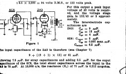
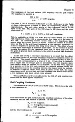
I found this artical in the Radiotron Designers hand book.
May give some good ideas.
Phil
From what i have read the 6AS7 is best run cathode bias.
The 12Ax7 is not a good driver for hard to drive tubes like the 6AS7 or 2A3 as there is a loss of high frequencies.
I found this artical in the Radiotron Designers hand book.
May give some good ideas.
Phil
Attachments
Hi,
The only point I completely disagree on is the statement about the 6AS7G being a "Twin Triode".
It is a "Dual Triode" hence other statements from RCA that the triodes should not be paralleled. (There goes my OTL)
http://www.clarisonus.com/Archives/TubeTheory/6AS7G.pdf
I also agree with azazello in that the 12AX7 is not a good choice for driving these kind of triode as HF roll of (among other things) is almost inevitable.
This kind of tube needs a beefy driver. To make life simple a driver that can operate well from lowish B+ is an advantage as the 6AS7G does not like high B+ either. Around 250VDC seems a good place to start.
Since the 6AS7 has a low mu of only 2 the driver also needs a medium to high mu.
A ECC88 seems quite a good candidate but I'm sure there are many others.
Ciao,
i like the 12ax7's in a guitar amp...or phono stage....
if i may, low mu triodes need more voltage drive, the driver stage can use a higher B+ than that of the output stage....
My driver stage is sitting at a bit higher B+ than the output stage, by about 30V. The 12ax7 as configured should provide the voltage swing required by the 6AS7.
My driver stage is sitting at a bit higher B+ than the output stage, by about 30V. The 12ax7 as configured should provide the voltage swing required by the 6AS7.
that is good, you may find that the higher the plate voltage of your driver,
the better for the sound, limited of course by plate dissipation....
The popular use of this type of tubes, like 6336, 6080, etc in the use with cathode polarisation is the hard use of fixed one, But always a good last one could give more efficiency. Many good amps use it. Azazello see it but with patience get better sound and not waste energy in heat.
Sorry, but all time I talk about HOW AMP SOUNDS,.... and how make amp better and with min. passive elements for real sound...Correct schematics /like schem. in this case/, IMO, isn't always criteria for good sounding and You can try more and more decisions of modes, tubes.... .
Last edited:
Sorry, but all time I talk about HOW AMP SOUNDS,.... and how make amp better and with min. passive elements for real sound...Correct schematics /like schem. in this case/, IMO, isn't always criteria for good sounding and You can try more and more decisions of modes, tubes.... .
I agree with you, just because a schematic is correct doesn't unquestionably mean it sounds good or bad.
But on the flip side of that, if an amp (or component of an amp) sounds good or bad, surely there is data to back that up.
- Status
- This old topic is closed. If you want to reopen this topic, contact a moderator using the "Report Post" button.
- Home
- Amplifiers
- Tubes / Valves
- 6AS7 SET amp discussion from Photo Gallery