I've recently recapped an aa-151 and replaced all resistors that were measuring out of tolerance. I've also replaced all the tubes. A little background of how this project all started though.
I inherited this amp and soon after noticed the el84's red plating. So a bit of googling educated me on what was happening. I wanted this amp up and running and also wanted to learn more about tube amps without having to take it to a repair shop so I took on the task of replacing the coupling caps myself. Soon after that I've since updated everything that needed replacing as mentioned above. The power caps were replaced with a 50/50 and a 30/30 JJ brand. All original caps (minus any ceramic) were replaced with CDE brand film, resistors are carbon film. The unit hums minimally and sounds good, however the main question i still need help with is the fact that I can't listen to it for more than 5 minutes without getting a headache/fatigue/sore ears. It's like there's some inaudible high frequencies being pushed but I cant say for sure as I don't have a scope or know what to look for. My ears are telling me something's wrong though. I've heard of maybe looking into 'bypassing the power caps' with smaller film ones but fail to understand what this would do to effect RF frequencies. Could it be any of the old ceramic caps in the tone section or any of the other carbon comp resistors that could be causing this?
any thoughts much appreciated....thanks!
I'm wondering if it's at all worth it to rig a bucking transformer for it to lower my wall voltage from ~125 average to 117. Overall the entire amp is running hotter than normal and filament voltages are up to 6.6ish. All other voltages are proportionally higher than the schematic. I've had to change out the 100ohm cathode resistor for the el84's to be a 200ohm instead. I've been told that I should have kept the 100 ohm in and address high voltages with chokes, additional power resistors upstream, etc. I just want to keep the unit as stock as possible as well as have a solution somewhat within my skill level. The schematic says 117v operation and i'm wondering if the addition of 7-8 volts is really causing that much of a problem i.e. crossover distortion, etc. (which is probably what it is). Also wondering what the average tech would do (in my area it's like $50 just to look at anything regardless of any work done).
You can adjust too high filament voltages with resistors. Check voltages then under load. You have a 310-0-310 PS trans and the Dynaco ST-35 with a SS rectifier instead of a tube uses a 330-330 so your B+ wouldn't be any higher than in that amp.
Both amps are hard on output tubes, so going to a form of fixed bias is the best solution.
The EFB fixed bias is the cheapest and actually better (sonically due to it's design) than regular fixed bias which has voltage supplied by a separate transformer supplying low voltage. You can do that also by buying the small trans, a diode bridge and a few resistors and pots.
It's easy to wire up and runs off the B+ to the output transformers.
New Modifications for the Dynaco SCA35 and ST-35
Dave's Lab
Also wondering what the average tech would do (in my area it's like $50 just to look at anything regardless of any work done).
Where are you at?
To keep it simple then try one 200-240 ohm resistor (200 ohms will be close to stock and a little bigger of course will reduce mA) with the cathode capacitor (so you will need a second one) per pair of output tubes as used in each channel. Look at the Eico HF-81 schematic. The Eico HF-81 used 165 ohms per pair of output tubes, but used a smaller PS trans. You will only need matched pairs per channel of EL84/6BQ5 tubes then.
Also do the bucking transformer mod with about a 5A transformer. A 12V one will get you just above 110V which will be great. You may need to make a 6V version for use when the line voltage goes down.
Still check your loaded filament voltages as you can guess too high is bad.
The Russian EV EB NOS output tubes will probably be the only new tubes to survive for a while verse other new production tubes. The EFB fixed bias or regular fixed bias would allow you to run other new production tubes like the JJ, New Sensor (EH, GL, or Tungsol) or the Psvane from China plus make the Russian NOS last longer.
As for the fatigue issue make sure you have the feedback wires at the speaker terminals hooked up and correctly. Check all the caps and resistors on that part of the circuit are okay also.
I have the same amp with no fatigue issues, but I'm in MB so can't help.
Last edited:
I've tried this at the advice of others. Nothing seemed to be happening there. As I've been listening also now the amp has become noticeably quieter and less fatiguing. Another thing that came of this was that i noticed the right channel weaker than the left. I've yet to measure the dual gang pot but assume it's off. For now i've just turned the right channel up to match the left. Having one quieter than the other no doubt was adding to things being 'off'.
Also, the amp probably *is* running fine (albeit with higher than usual wall voltage), and i've been able to listen to it longer. It's just concerning me the actual health of the amp. Everything's been changed except the ceramic caps and any resistors that appear to be in spec, all new tubes (NOS except brand new JJ EL84), tone circuit untouched (treble pot is also measuring a bit high at 1.3meg) and all voltages are equal more or less across channels (just all proportionally higher due to 125v at wall) and of course the much higher 420v b+ due to raising the cathode resistor on EL84's.
Maybe this amp just doesn't do it for me? I've been impressed with it no doubt since coming from Solid State, but fear it to be to slow (tube rectified) or lacking the kind of clarity i'm use to. Also maybe something even simpler like a dynaco amp with a much simpler circuit (no tone controls) and one with healthier pots and all newer parts, etc.
Make a Bucking Transformer, as whatever amp you have the Filament Voltages will be too high!
The caps (mainly coupling) are probably breaking in along with the new tubes and so the sound may even get better!
You can easily jumper out the tone controls with a switch to see that affect. There is a fellow in Canada (I think Montreal) that does basically that and afterwards people rave about the AA-151 as he rebuilds amps.
Changing the other components (the only thing left is the Output Transformers) that would have any affect is the Output Transformers, but new ones of the same construction, design etc. wouldn't make a bit of difference, as Age Doesn't change them.
You basically have the same circuit as the Dynaco SCA-35 an integrated , just different tubes.
The Eico HF-81 has the same circuit, but it's tone controls are better done, and it's power supply is good with no resistance added like the AA-151. You have better Output Transformers though, along with the ones on the Dynaco ST/SCA-35 (all the same) so have patience and hang in there!
You can do the diode mod which is adding SS diodes in series to pins #4 & 6 of the rectifier tube which will help it last as it takes some of the load off of it while keeping the slow warm up the the GZ34/5AR4 is famous for. It should improve the bass a little.
Then you can experiment further by removing the tube and jumpering in SS diodes. Use the newer faster & quieter UF4007 for a few cents more all mentioned over the older IN4007.
You can also buy aftermarket plug in tube SS rect. subs. Google. Copper ones.
The mod shown in the diagram uses unused pins on the rectifier tube to mount the SS diodes. Pay attention to the polarity.
The mod also helps the rectifier tube last when you have a power failure where it flashes off and on which someone can accidentally do with your amp.
Besides having nice iron the AA-151 has another plus in that it's P2P wired and has lot's of room to work on it.
Last edited:
New question about the tone controls
Recently I have replaced the original PEC tone packages with discreet components.
The question I have is why each knob seems to operate differently now. The treble seems responsive as it should but raises the volume when turned up whereas before this wasn't the case.
Also, the bass doesn't seem to do as much as it used to. If turned all the way down then I can detect a drop in bass some, but not like before. From half way to all the way up doesn't seem to do much either.
I've also replaced the pots from original as well. They are alpha dual-gang 1meg. Although the treble pot is close to 1meg, the bass side for both Left and Right are closer to 800K.
Could I need to wait for the parts to break in? It doesn't seem like something that time would help.
Any clarification on why this would be different or how to troubleshoot would be much appreciated!
Bumping this thread.
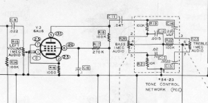
I've also attached a pic of the new tone control setup for review. As mentioned, the Bass control isn't very interactive, and the amp seems woofy when controls are at 12 o'clock and the treble boosts volume when turned up noticeably. I can't recall too well how it sounded when the old packaged controls were in there but it seemed like they did more than they are now. I also believe I have wired up the new tone section properly based on the schematic.
I've also attached a pic of the new tone control setup for review. As mentioned, the Bass control isn't very interactive, and the amp seems woofy when controls are at 12 o'clock and the treble boosts volume when turned up noticeably. I can't recall too well how it sounded when the old packaged controls were in there but it seemed like they did more than they are now. I also believe I have wired up the new tone section properly based on the schematic.
An externally hosted image should be here but it was not working when we last tested it.
You might need a squarewave generator and scope to sort this out, because passive tone controls often don't work like you expect them to. As an example, the Dynaco SCA-35 kit assembly instructions require deliberately offsetting the knobs on the control shafts to achieve flat frequency response at the straight-up setting.
Edit: I see what looks like .0022 uF caps in four places, but the schematic shows them in only two places. And I don't see any 220pF caps, which the schematic also shows in two places.
Edit: I see what looks like .0022 uF caps in four places, but the schematic shows them in only two places. And I don't see any 220pF caps, which the schematic also shows in two places.
Last edited:
Above I did mean to say they are audio taper pots. I had filed a "D" into the shafts at 10% of their values based on the baxandall tone circuit being at "flat" there when at half rotation. I compared the rotation of the older pots as well and they follow a similar pattern. Earlier I had mentioned the pots were both under 1M too. The treble pot is closer to 1meg, the bass pot for both Left and Right are closer to 800K. That being said, the bass isn't that responsive. I only hear noticeable cut between 9 and 7 o'clock and noticeable gain from about 230 to 5 o'clock. So that right there doesn't suggest needing a precise 12 o'clock setting if it's only doing stuff at the start and end. I've also read that to get a "flat" response, most people with these amps need to set the treble at about 130-2 o'clock, which is what i'm experiencing as well.
So far tube rolling hasn't much changed the sound either:
EL84 - using JJ right now, also tried these but they seem darker
www.thetubestore.com - Preferred Series 7189 (Premium EL84) Audio Tubes
GZ34 - using JJ right now, although vintage mullard and sovtek new prod. slightly changed the sound. JJ is a little mellower and the others more bright and punchy. Yes, rectifier tubes have changed the sound for me even more that the preamp tubes.
6au6 - tung-sol NOS from the 50's. Also had NOS RCA's but not much difference.
6eu7 - have both new prod sovtek and NOS RCA. I notice voltage differences in the circuit between the two but not much sonically.
6an8a - NOS RCA, two different sets. Again, not much difference here.
Seems like out of the above, the EL84 swapping provides the most difference in sound, which you might not expect. You'd think preamp tubes would be where it's at. Also, rectifier swapping comes in second for sound.
To answer the question about the components, you're seeing both sides of the amp there (left and right channels).
I've attached the schematic here to help visually match up what's going on in the picture. I was originally going to use a perf board to mount all the components to but then was unable to imagine a way to attach all that, so soldering directly to the pots it is. Also, it makes it easier to follow the schematic. Makes you appreciate how say a fender deluxe schematic can be transformed into the eyelet board layout they have!
All those caps are panasonic film. Is there a way to hear the amp flat to rule out tone controls that doesn't involve to much work? Ideally I have a reference tone and A/B the amp in and out, adjust the tone until it matches, and then see where "flat" is. Right now the biggest thing is the bass being too present. Almost like someone having turned it up too much and getting that really overwhelming mids sound. Maybe the combination of tubes and the new components (which are a year old at this point) are making for an unfavourable sound?
Your schematic differs from the original Heathkit schematic I retrieved. See attachment. Based on what I know about passive tone control design, yours probably is incorrect. If you want to hear the amp sans tone controls, just replace the tone stack with a simple resistive voltage divider of, say, 390K and 47K attached to the right side of C11 (Heath schematic) with its tap going where the treble pot wiper went. This divider should yield roughly similar attenuation relative to passive tone controls set flat. Tube rolling is a fruitless exercise in most cases. You can make a lot more progress by spending the money on books and test equipment instead.
Attachments
I do have the original manual as well which looks like the screen you posted. Same tone network too, just different layout. One thing that caught my eye was the 220uuf value for the treble side.
In my screenshot, the left and right side of the pot has .0022uf values, which is what I have put in.
In your schematic, it outlines the left side as being 220uuf (which is 220pF, which is 0.00022uF). I'm wondering which is right? How much difference could that one value make (220pf vs 2200pf)?
In my screenshot, the left and right side of the pot has .0022uf values, which is what I have put in.
In your schematic, it outlines the left side as being 220uuf (which is 220pF, which is 0.00022uF). I'm wondering which is right? How much difference could that one value make (220pf vs 2200pf)?
- Home
- Amplifiers
- Tubes / Valves
- Heathkit AA-151 troubles