Hi There
I have seen much people who says, low idle current give tube more detail, others say put it in class A to get better sound.
What are your experience with idle current, I have a cascode mosfet on plate so I have a horizontal loadline, because of this distortion is low make tube sound hars/hard buit with a lot detail and deepness.
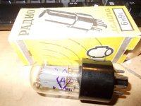
I did use a 6H9C, I have heart this are hars sounding tubes.
A penthode 6J9N in triode mode last time did make warmer sound, what I do like, this 6H9C do not, the 6H8C will do sound warmer, more what I like.
regards
kees
I have seen much people who says, low idle current give tube more detail, others say put it in class A to get better sound.
What are your experience with idle current, I have a cascode mosfet on plate so I have a horizontal loadline, because of this distortion is low make tube sound hars/hard buit with a lot detail and deepness.
I did use a 6H9C, I have heart this are hars sounding tubes.
A penthode 6J9N in triode mode last time did make warmer sound, what I do like, this 6H9C do not, the 6H8C will do sound warmer, more what I like.
regards
kees
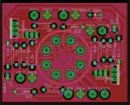
Attachments
Last edited:
Idle current about 2 ma /more current - big sound, IMO/
But I prefer 6SN7 with 8 - 10 ma /Loftin-White two stages with adjustable gain from 20 to....max/.
Thanks
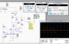
I have now put it on 0.5 mA and it do sound nice, don,t forget I have a horizontal loadline, not a resistor loadline, this change things.
2 mA put 0.4 watt dissipation on tube when 200 volt on plate. I go try out what sound it delivers.
I have to use a high mu triode because of it is a mosfet hybride amplifier, it do the full voltageswing needed.
regards
kees
Last edited:
A 6H9C on 2 mA is not so good, cahtode resistor is to low make just 1.45 v negative, resistor 680 ohm is needed for 2 mA.
I let it on 0.5 mA for a while, looks like it has more detail and deepness.
Still a penthode do better.
After a longer time I did look again on the current who has to be 2.3 mA but I did say about the cathode resistor make not enough negative (negatief needs -2 volts, input signal 1 volts max).
Solution is higher voltage, this tube likes high voltage, make it sing.
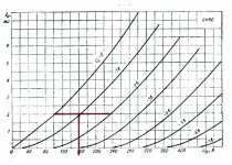
From the plate curves it would appear that at Ip = 2mA you would have Ep = 160V and grid bias would be -16V. Your cathode resistor would have to be 8k ohms.
From the plate curves it would appear that at Ip = 2mA you would have Ep = 160V and grid bias would be -16V. Your cathode resistor would have to be 8k ohms.
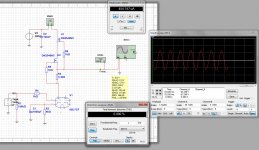
When I do this I get not 2 mA with 8 k ohm, I have included a measurement with plate voltage 260 volts, and 1 K ohm cathode resistor I get 2.04 mA.
When I do in sim 8 K ohm and 160 volts then i get no more then 0.227 mA that is quite low??, I did read somewhere these tubes need high voltage to sing properly.
Do I miss something here, don,t forget I do use cascode fets so loadline is horizontal, things change..
Now the amp plays with 260 volts plate voltage and 1 K ohm cathode resistor and I get 2.04 mA max is 2.04 volts on 1k resistor.
Or do I have bad tubes, she are in original box.
regards
kees
Attachments
Last edited:
R4 should be on the grid, not the grid leak resistor!
Valves are very tollerent and do not need special component values.
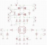
This is drawn there I have did in final schematic in eagle corrected I did see, also is now 1k ohm.
I still do not get on why cathode resistor 8 Kohm and 2 mA and 160 volts? I do not get more then 0.227mA?, I have now 260 volts (plus minus) en have with 1 K ohm resistors 2.04 mA.
So what is problem?
thanks.
Attachments
Last edited:
I would guess that you have a problem with the design of the CCS. Try breadboarding the circuit to test it.
Hi Palustris
The CCS do work fine because the voltage on the tube plate is in my case now 260 volts and then the tube draws 2 mA with a cathode resistor of 1 K ohm, when CCS do now work oke, I get never the voltage on plate I want, but maybe i miss something,, I go try a MU-stage to see what happens or a single plate resistor, but I think the same will happen. 8Kohm for a source resistor will never get me to 2 mA.
Maybe I do have bad ones?
Attachments
From the plate curves it would appear that at Ip = 2mA you would have Ep = 160V and grid bias would be -16V. Your cathode resistor would have to be 8k ohms.
I think you might be reading the grid voltages incorrectly from the graph.
Your -16v will actually be -1v (Cyrillic -1B).
-16v on one of these tubes will cut it off almost completely.
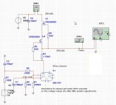
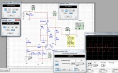
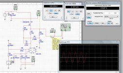
Did drawn a mustage in sim, and use a 6sl7 tube (same) but with 160 volts on plate I get not 2 mA like yours, only when make the cathode resistor very small I get there, but voltage over that resistor is also very low get not much negative voltage.
with 220 ohms on cathode I get 2.1 mA when i do 1Kohm I get 1.1 volts, 1.1 mA, both with 160 volts plate voltage.
So CCS is oke in 9
with 220 ohms on cathode I get 2.1 mA when i do 1Kohm I get 1.1 volts, 1.1 mA, both with 160 volts plate voltage.
So CCS is oke in 9
Attachments
I think you might be reading the grid voltages incorrectly from the graph.
Your -16v will actually be -1v (Cyrillic -1B).
-16v on one of these tubes will cut it off almost completely.
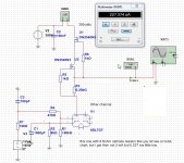
Now we get somewhere
 then I get more reliable readings.
I did also not see the B in graph, now it make more sense because I have 2 volts on the resistor
and get 2.04 mA/260 volts on plate (1.1 mA 1Kohm 160 volts), recommended by a russian guy here who say do not torture this tube
with 150 volts, it need voltage to sing, so I did now, but it can not go swing more then 50 volts, now it will
limit on supply rail, but for now in test it is not a problem, 40 volts on speaker is quite loud also..
Last edited:
Now we get somewhere
OK, now we are all learning something too!
I never used the 6H9C but now I know it is similar to a 6SL7 it all makes sense.
And I think you are correct that there is no need to burn up the tube.
Recommended operating points are Ep = 250V, Ip = 2.3mA, Eg = -2V for mu = 70 and Rp = 44k ohms, plate dissipation = .575W
Max plate dissipation is 1W
I would think that with an LED bias at -1.8V and your CCS set for 2mA you should get a plate voltage of about 225V for a plate dissipation of .45W.
I go try the led, and put plate voltage on 250 volts, higher voltage seems to give better sound, but this is just tryout.
Thanks for help, all of you.
Another thing to remember is that your sim tube model is most probably not very accurate; almost no tube models are.
So your sim result may deviate quite a lot from reality.
Jan
I do remember that, models can not 100 procent accurate, a lots of incoming things are make things different then sim, even Mr Murphy etc, and so building it is the only good way.
But, the sim programs has serve me wel in blowing a lot less components.
I have put in green leds, tube take now 249 volts on plate, draw 2.22 mA
I let it this way and listen a couple weeks to it.
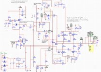
I do go build also a hybrid version with a 3x compound output, then I can also try a lot of tubes by tampering the mosfet local current feedback.
And so we keep busy.
Attachments
Idle current about 2 ma /more current - big sound, IMO/
But I prefer 6SN7 with 8 - 10 ma /Loftin-White two stages with adjustable gain from 20 to....max/.
Do you mean SRPP? 6SN7 in a cascode will do also good I did heart.
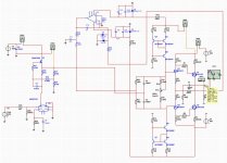
This amp I do play music with, it is there for say 6 years

But now it is with the 6H9C tube instead of the penthode in schematic, this penthode I do still like more, in this case with a mosfet gyrator, but last I do use CCS or MU who do wel.
Amp tube drivers are dc coupled to te mosfets, and a servo keep track of it coorect automatic for driver tube aging.
regards
Attachments
- Status
- This old topic is closed. If you want to reopen this topic, contact a moderator using the "Report Post" button.
- Home
- Amplifiers
- Tubes / Valves
- 6H9c Idle Current.