Hi,
What team?
Or do you expect me to teach the world how to chemically merge Au atoms to Ags...??
Please...?
Cheers,")
fdegrove, your brief feedback is appreciated but why not share your knowledge with the team please...forgive me, I'm trying to learn here.
What team?
Or do you expect me to teach the world how to chemically merge Au atoms to Ags...??
Please...?
Cheers,
Konnichiwa,
So it seems. If not Russia has huge cold war stocks of them.
Either Reflektor or Saratov.
Russia.
Good valve?
Simply wire as triode. Drops in for 417A with (of course) different pinout and slightly higher Mu and Ra.
Sayonara
mcs said:
Still in current production?
So it seems. If not Russia has huge cold war stocks of them.
mcs said:
Who?
Either Reflektor or Saratov.
mcs said:
where?
Russia.
mcs said:
why?
Good valve?
Simply wire as triode. Drops in for 417A with (of course) different pinout and slightly higher Mu and Ra.
Sayonara
Silver Stealth said:fdegrove, your brief feedback is appreciated but why not share your knowledge with the team please...forgive me, I'm trying to learn here.
Geeesh! Why must we all feel guilty for trying to learn? What's wrong with this picture? Learning is what DIY is all about.
You shouldn't be asking for forgiveness for trying to learn.
6S45P-E
I have been using a pair of 6S45P-Es as power valves (don't laugh, my speaks are >100dB/1W, are yours?) quite satisfactorily for more than a year.
The design can be found here
www.sempermusica.com
I found that ferrite beads at the grid pins were not enough to kill oscillations (whereas they were sufficient for 3A/167Ms). I ended up with 100 ohm carbon composition hard up against one grid pin valve base tag and the other grid tag clipped flush to the base. No stoppers on unused cathodes nor any prophylactics on the heaters. 200MHz Tek scope shows a clean trace and the sonics are fine. However the sound is a little on the transistory side and when Peter Millett tested one of these valves at my operating point (195V @ 45mA) he found a little too much 3rd and 5th harmonic in the spectrum. As KYW has observed, these hot little Russkie babes should really be run on less juice - 10-15mA - when the 3rd & 5th disappear into the noise floor.
Brian.
So Brian, and KYW can you describe your preferred operating point in totality for this tube? Sounds like I am still running too much current (about 26mA at present).
Brian, when you say grid tag clipped flush to the base, do you mean the unused grid tag soldered to the centre pin (which is o/cct) of the tube base?
Oh for a 200Mhz cro...maybe I can borrow one from work over the weekend...
And how well filtered are your PSUs? Using CRC, CLC, or other? At present I have CRCC with the first and second Cs at 220uf, R is 665R and third C is 200uf mounted in the main chassis - the CRC are in a seperate box with the mains transformers). A high DCR choke might be the ticket - anyone care to recommend inductance value that won't constrain the dynamics?
Cheers, Kendrick
Konnichiwa,
I started with the 6S45 @ 150V/30mA and worked my way down step by step to 12mA. Later I switched to WE 437A and there I found that going further down to around 6mA like seen in some Japanese schematics from MJ improved things further.
All this was as Driver for a 300B, CL coupling to 300B, R or Choke load on 6S45/437A.
The 300B PSU was CLCLC with a "tuned" first Inductor to maximise 100Hz rejection and then RC to 6S45/437A, all PSU Cap's Film types 47uF except first which was 1uF Foil & Film, 5R4/5U4/274A rectifiers.
Sayonara
Silver Stealth said:So Brian, and KYW can you describe your preferred operating point in totality for this tube? Sounds like I am still running too much current (about 26mA at present).
I started with the 6S45 @ 150V/30mA and worked my way down step by step to 12mA. Later I switched to WE 437A and there I found that going further down to around 6mA like seen in some Japanese schematics from MJ improved things further.
All this was as Driver for a 300B, CL coupling to 300B, R or Choke load on 6S45/437A.
Silver Stealth said:And how well filtered are your PSUs? Using CRC, CLC, or other?
The 300B PSU was CLCLC with a "tuned" first Inductor to maximise 100Hz rejection and then RC to 6S45/437A, all PSU Cap's Film types 47uF except first which was 1uF Foil & Film, 5R4/5U4/274A rectifiers.
Sayonara
Hi,
From reading his website, I think he meant it literally...
It does away with the stub aerial to some extend at that end.
No idea on how effective it really is...
Cheers,
Brian, when you say grid tag clipped flush to the base, do you mean the unused grid tag soldered to the centre pin (which is o/cct) of the tube base?
From reading his website, I think he meant it literally...
It does away with the stub aerial to some extend at that end.
No idea on how effective it really is...
Cheers,
Hi Kendrick and fdgrove
I just snipped the valve holder tag corresponding to the unused grid pin flush to the base of the holder and, with the gridstopper on the other grid tag, my amp behaves beautifully. Other environments may make further precautions necessary but I have had no problems reported from others who have built Spuddo.
The PSU is LCLC with 47uF and 200uF (parallel sections of Cerafine 100 + 100). The input choke is a low DCR Lundahl and the second a 150 ohm DCR cheapie from Maplin. The amp is built exactly as per the diagram on my webpage. The mains is shunt filtered using KYW's TNT design.
And that's it.
Very effective for me.
The "best" distortion spectrum from Peter Millet was 10mA @ 150V AFAIR and I believe the results can still be found at
http://pmillett.addr.com/pentodes.htm
Brian.
I just built the 6c45pi amp found at http://digilander.libero.it/paeng/pae.htm
I am realy impressed with how this little amp sounds
and the Black Gate cathode bypass haven't even had
a chance to breakin.
Woody
I am realy impressed with how this little amp sounds
and the Black Gate cathode bypass haven't even had
a chance to breakin.
Woody
6c45 phono amp
Hi,
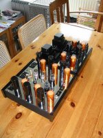
with the 6C45 i built a phono amp. The tube is simply "invented" for that purpose.....
As stated in other replies: low on voltage and milliamps. And i also had to use gridstopper (used a tantalum 150 ohm).
The amp is built on 2 chassis. One for audio and the other is the powersupply. Picture included.
Schematic in words:
6C45 - RIAA - 6C45 - interstage - 6SN7 - output transformer.
Why: because there is only one tube manufacturer of these tubes. So: take it or leave it. With a 6SN7-stage after the phono-amp itself i can finetune the tonal quality with the abundance of all available 6SN7's. At this moment i'm using KenRad's for the 6C45 does sound a little cool and the KenRad's just bring the total sound back in balance.
Powersupply: massive. But now the amp is extremely quit and stable.
Reinout
Hi,
with the 6C45 i built a phono amp. The tube is simply "invented" for that purpose.....
As stated in other replies: low on voltage and milliamps. And i also had to use gridstopper (used a tantalum 150 ohm).
The amp is built on 2 chassis. One for audio and the other is the powersupply. Picture included.
Schematic in words:
6C45 - RIAA - 6C45 - interstage - 6SN7 - output transformer.
Why: because there is only one tube manufacturer of these tubes. So: take it or leave it. With a 6SN7-stage after the phono-amp itself i can finetune the tonal quality with the abundance of all available 6SN7's. At this moment i'm using KenRad's for the 6C45 does sound a little cool and the KenRad's just bring the total sound back in balance.
Powersupply: massive. But now the amp is extremely quit and stable.
Reinout
Attachments
- Status
- This old topic is closed. If you want to reopen this topic, contact a moderator using the "Report Post" button.
- Home
- Amplifiers
- Tubes / Valves
- 6c45pi : sonic utopia or sonic hell?