
I also need help, I need to change 6ca7 tubes and need help how to adjust bias after that.
Also I want to know is there any different in adjust bias procedure depends of year of production or is the same for every year. I think my amp is from 2006 or 2007 year.
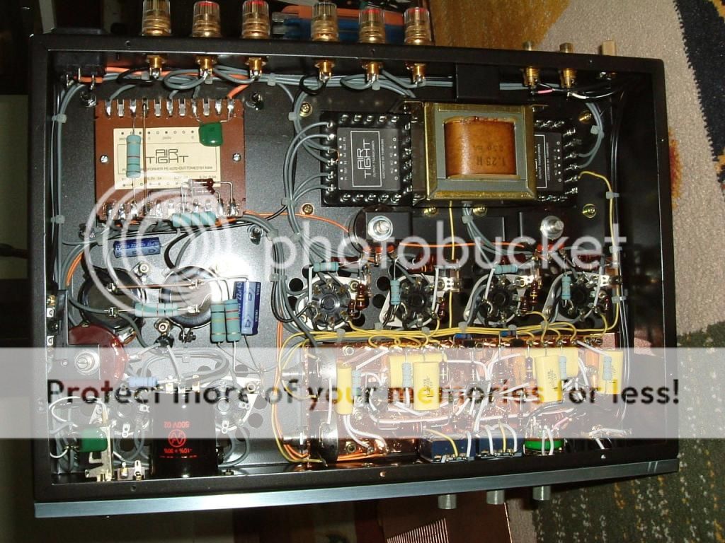
Picture is from net but the amp is same as mine, can someone draw lines where i put + and - of voltmeter
Also I want to know is there any different in adjust bias procedure depends of year of production or is the same for every year. I think my amp is from 2006 or 2007 year.
Picture is from net but the amp is same as mine, can someone draw lines where i put + and - of voltmeter

ATM-1 Biasing
Hi this is not so elegant with this amp, what you need to do is measure over the OPT primaries!
First you measure the ohmic resistance of both primary halves (yes, they WILL differ quite substantially!!) and then you calculate the corresponding voltage across considering a 45 mA (or 50 mA, depending on your preference how fast you want to cook up your new tubes")
You need to do this a couple of times, as B+ will vary on the bias current chosen, which will then influence the bias for the other tubes already done. You will need 2 voltmeters to balance out one channel. Better, find on eBay these 4 position Octal digital bias meters, they have 4 octal plugs you put in the amp, in which you insert your EL34 tubes / 6CA7. Then, just cycle through the 4 switch positions while adjusting the bias. This way it's done in no time. Well worth the investment. Let me know if you can't find it, and I'll point you at a good vendor.
Also, you need to adjust the driver symmetry. For that you would need a distortion analyzer. There is no real good facility to measure that other than measuring the D%. If you don't have such eqmnt, don't touch I would say, but if you change the ECC82 (I have E80CC) you in fact need to..
More questions: tubes.leonard@hetnet.nl
Leonard
Hi this is not so elegant with this amp, what you need to do is measure over the OPT primaries!
First you measure the ohmic resistance of both primary halves (yes, they WILL differ quite substantially!!) and then you calculate the corresponding voltage across considering a 45 mA (or 50 mA, depending on your preference how fast you want to cook up your new tubes
You need to do this a couple of times, as B+ will vary on the bias current chosen, which will then influence the bias for the other tubes already done. You will need 2 voltmeters to balance out one channel. Better, find on eBay these 4 position Octal digital bias meters, they have 4 octal plugs you put in the amp, in which you insert your EL34 tubes / 6CA7. Then, just cycle through the 4 switch positions while adjusting the bias. This way it's done in no time. Well worth the investment. Let me know if you can't find it, and I'll point you at a good vendor.
Also, you need to adjust the driver symmetry. For that you would need a distortion analyzer. There is no real good facility to measure that other than measuring the D%. If you don't have such eqmnt, don't touch I would say, but if you change the ECC82 (I have E80CC) you in fact need to..
More questions: tubes.leonard@hetnet.nl
Leonard
thank you Billy Pilgrim for your diagram. a little part is missing in the bottom of your picture. can you send it please ? thanks in advance. Matthieu
That's all the picture I have. The missing text is 50u + 50u @ 550v.
Hi this is not so elegant with this amp, what you need to do is measure over the OPT primaries!
First you measure the ohmic resistance of both primary halves (yes, they WILL differ quite substantially!!) and then you calculate the corresponding voltage across considering a 45 mA (or 50 mA, depending on your preference how fast you want to cook up your new tubes
You need to do this a couple of times, as B+ will vary on the bias current chosen, which will then influence the bias for the other tubes already done. You will need 2 voltmeters to balance out one channel. Better, find on eBay these 4 position Octal digital bias meters, they have 4 octal plugs you put in the amp, in which you insert your EL34 tubes / 6CA7. Then, just cycle through the 4 switch positions while adjusting the bias. This way it's done in no time. Well worth the investment. Let me know if you can't find it, and I'll point you at a good vendor.
Also, you need to adjust the driver symmetry. For that you would need a distortion analyzer. There is no real good facility to measure that other than measuring the D%. If you don't have such eqmnt, don't touch I would say, but if you change the ECC82 (I have E80CC) you in fact need to..
More questions: tubes.leonard@hetnet.nl
Leonard
I installed a 1R resistor on the 6ca7 cathodes and measure that....
AirTight biasing
@billy
Ofcourse that is the obvious thing to do, mount cathode resistors. But I am quite reluctant to start soldering and poking around in this piece of japanese art. I bought a 4-way tube bias meter on eBay now, 4 octal sockets, a digital meter & 4-way switch in a little box, battery powered. Now, this is easy! Read the bias in mA directly from the meter, cycling the switch through the four positions until all is OK. Much more convenient than measuring over the OPT or even the added resistors.
It seems though that soldering will become inevitable at some point as my psu electrolytics (Nichicon Audio Professor) are drying out. The neoprene sealings start to crack, and the pressure valves are playing up a bit. There will be a day I need to replace them but with what? Sent an email to Mr. Atsushi Miura for some advice, I woul like to understand what he's using as a service replacement part, or what he's using in the ATM 1-S..
I also tend to buy 4 way bias meter. Can you tell me what will be the good read for mA for each tube (I mean how much mA)
What you call pressure tube I don t understand is it 5AR4
If it is the substitution tube is TUBE ELECTRON 5ar4 made in China. That dealer from Serbia sell as original substitute receive directly from ATM.
Rest tube can be EH and SIEMENS is what they said and also some other brand if you prefer.
reg
What you call pressure tube I don t understand is it 5AR4
If it is the substitution tube is TUBE ELECTRON 5ar4 made in China. That dealer from Serbia sell as original substitute receive directly from ATM.
Rest tube can be EH and SIEMENS is what they said and also some other brand if you prefer.
reg
There is a simple and elegant solution when measuring bias. Simply put your DVM set to 200 mA between +B and the anode, pin 3 at the tube you want to set bias for. No need to calculate anything, you see the bias current directly. The resistance in the instrument is so low, that the resistance of the OT don´t matter.
This is how they bias guitar amps, read it in a book by the guru Gerald Weber, of Trainwreck fame
This is how they bias guitar amps, read it in a book by the guru Gerald Weber, of Trainwreck fame
@Nikolazec
Hi, 45mA is OK. The rest of your email I do not understand.
I did not use the word "pressure tube".
I used the word "pressure valve" which is a pressure relief valve under the neoprene sealing of most large electrolytic capacitors. When the cap gets old and the neoprene starts to crackle, this valve starts to come out sometimes which is kind of an indication the soldering iron needs to be heated as the cap needs to get replaced.....
Cheers Leonard
@seppoa
It is not that simple when you do not want to solder in your amp. One typically does not poke around in an AirTight amp, as you also would not in an AudioNote Japan or similar amp. So you need to use a method which is not intrusive. Putting the meter between the plate and B+ is kind of obvious, but not in an amp like this!
It is not that simple when you do not want to solder in your amp. One typically does not poke around in an AirTight amp, as you also would not in an AudioNote Japan or similar amp. So you need to use a method which is not intrusive. Putting the meter between the plate and B+ is kind of obvious, but not in an amp like this!
@seppoa, I see what you mean now, just bridge the OPT primary with the mA meter. This way you only measure the plate current and not the total (i.e. including screengrid). Anyway, the deviation would me minimal, so I guess the methodology would be usable. Nevertheless, the bias meters available make life very easy as you can cycle easily through the 4 bias points monitoring all of them. As soon as you change one, the rest will change as well (B+ variations) so having a 4 position switch makes life easy
Yes, I have not taken the G2 current in consideration, and of course this current is not measured with my method. But as you say, this current is unimportant compared to the anode (plate) current.
In case of this particular amp, the bias pots are all at the bottom, and my method should be quicker and as good as when using bias adapters
Cheers and enjoy your amp, with good music.
In case of this particular amp, the bias pots are all at the bottom, and my method should be quicker and as good as when using bias adapters
Cheers and enjoy your amp, with good music.
@triodes4ever
No need to solder anything. Just clip one probe to B+ and the other to pin 3 at the tube sockets.
Of course this can be dangerous if you do not have skills to work with high voltage. But according
to the picture all is easily accessible. Just be careful.
This is very dangerous, since the DVM's internal fuse can NOT break such a high DC voltage. NEVER try this.
Last edited:
@rayma
Thanks for giving your advice. But as I stated, this is not for unskilled persons. This advise was originally given by Gerald Weber in a book about dealing with guitar amps. And the persons dealing with guitar amps are less skilled than the most of us, or maybe equal. The fuse in a DVM should be capable of dealing with 500 volts DC even if the claim is 250 V AC. The DC rating is lower than the one for AC.
But if there are any doubts, please do not use my advice, OK.
The fuse in a DVM should be capable of dealing with 500 volts DC even if the claim is 250 V AC.
The DC rating is lower than the one for AC. But if there are any doubts, please do not use my advice, OK.
Skilled persons would never do this, since we want to live, only a neophyte would. Most such fuses are rated at only 32VDC.
Last edited:
- Home
- Amplifiers
- Tubes / Valves
- AirTight ATM-1 Schematic