I would consider even a bit less, about 650V, under load (also considering some volts dropped into the OT). I would still run it at 60 mA. Increasing the current to 80 mA I guess will result in lower "usable" Pout as that driver will be not able to drive the 845 into positive grid field with low distortion.
To get it right with you actual 845's I would start with 1K plus +10R precision reistor to measure the current + a 1K variable resistor, all in series. Once you know what value you need you change them with the nearest convenient value.
I agree with MelB, that 20 uF cathode bypass is a bit small. I would use 100 uF. It's cheap if you use electrolytics....However initially you don't need to change it if you run measurements at 1KHz only.
Last edited:
Check the current ratings of the 5AR4 at these voltages, you might want to consider a pair in parallel or a 5U4 instead particularly with modern examples which generally aren't too reliable at these voltages. You can improve the ruggedness of the 5AR4 considerably by installing a pair of UF4007 or similar diodes in series with the plates.
@45
I'm missing something about the lower operating point you suggest. If you run at 80mA vs. 60mA you get into a positive grid voltage when your anode voltage is higher and therefore your grid current is lower requiring less drive current? Or do I have that backwards?
It seems counter intuitive that a lower operating point would yield more power out?
I was simply saying that one is not going to get a real benefit from the increased dissipation as the output tube will first run into grid current than cut-off and the clipping will be harder. The difference in anode voltage will only be about 10V between the two operating points I guess, without considering various drops along the supply and OT. Assuming 650V total, for 575V at - 75V bias you would get about 60 mA and for 75V swing it will be still several milliamps, on average almost 10 mA, away from the cut-off with 5K. It could even run at lower primary load without problem, for example if the speaker load drops to 6R the max Pout would not change significantly. However he can try both 60 and 80 mA and decide what he likes. The Pout will be a bit less, equal or a bit more mostly depending on the max THD you want to accept otherwise if you consider the absolute max 10% THD the lower current might just give a bit more power for any secondary load equal to or greater than 6R!
Last edited:
Hi
Thank you all for the help!
I'm still waiting for some parts to arrive.
meanwhile I'm trying to figure out what the best design for the filaments power supply.
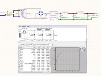
Please see the design.
Tried to simulate, but the soft does not have the differential model for the choke.
One of the questions is, should I apply the differential choke immediately after the first cap as in the schema or should I apply it at the output?
Thanks
Thank you all for the help!
I'm still waiting for some parts to arrive.
meanwhile I'm trying to figure out what the best design for the filaments power supply.
Please see the design.
Tried to simulate, but the soft does not have the differential model for the choke.
One of the questions is, should I apply the differential choke immediately after the first cap as in the schema or should I apply it at the output?
Thanks
Attachments
Help on IT drive stage
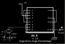
I'm trying to draw the IT drive stage but I'm not sure if my calculations are correct this IT for Alt S connection have a 18mA rated.
should I set the bias to 18mA or to be safe, go for a lower set point like 15mA or 10mA. I'm trying not to burn the IT.
I real appreciate your help!!
Thanks.
I think you will get about 7W max with 610 total supply voltage at 60 mA and 5K.
If you go for the LL1692a/18mA you can experiment the connection ALT T (36 mA and 35H) with the 6C45 or the connection ALT S 4:3.5 ratio with the D3a.
The connection ALT S will allow 18 mA that are enough for the D3a with 125H primary inductance.
With the 6C45 and LL1692a ALT T you should need less than 0.7 V RMS for full power. With the D3a and LL1692a ALT S you will need about 1 V RMS. For 1W output you will need about 0.25 V RMS in the first case and 0.37 V RMS in the second. This could be enough if you use a modern CD player and 90 dB efficient speakers in most cases without adding a step-up input transformer. I would first try this two stage amp with normal volume control at the input and then if you feel the gain is not enough you can think about increasing the gain further.
I'm trying to draw the IT drive stage but I'm not sure if my calculations are correct this IT for Alt S connection have a 18mA rated.
should I set the bias to 18mA or to be safe, go for a lower set point like 15mA or 10mA. I'm trying not to burn the IT.
I real appreciate your help!!
Thanks.
Attachments
Last edited:
Hi!
You can safely run the IT at the rated current of 18mA. In fact these transformers have some margin. Up to 20mA would still be ok.
There is no danger to burn such transformers at these currents. What happens when you apply too much DC is core saturation. But that kicks in gradually.
Best regards
Thomas
I'm building an amp based initially on the schematic and 845 operating points of the first circuit you posted. I'm curious if you have a schematic of your power supply.
Hi jervill,
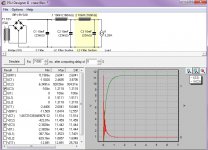
For now I'm using this power supply,later on maybe I review this design.
You have a good tool to simulate the power supply.
Download
Regrads,
MFF
Attachments
Hi
I tried to simulate, but the soft does not have the differential model for the choke.
One of the questions is, should I apply the differential choke immediately after the first cap as in the schema or should I apply it at the output?
Thanks
The inrush current caused by the capacitor can damage the tube filaments?
In the PSU simulations appears to be on the order of 1,2A.
I'm doing this right?
I appreciate any help!!
Regards
MFF
Attachments
I can't comment on your exact question but as an aside, what 845 are you using? I'm using, for this and the foreseeable use of the amp I'm working on, the shuguang 845b for cost and availability considerations. These only draw 2.5A, which I didn't realise until I breadboarded the filament supply and measured 2.475A draw. (I confirmed this with the shuguang spec sheet, which I should've done in the first place.). I didn't realise so all my sims were out and had to be re-adjusted. Just thought I'd mention.
I can't comment on your exact question but as an aside, what 845 are you using? I'm using, for this and the foreseeable use of the amp I'm working on, the shuguang 845b for cost and availability considerations. These only draw 2.5A, which I didn't realise until I breadboarded the filament supply and measured 2.475A draw. (I confirmed this with the shuguang spec sheet, which I should've done in the first place.). I didn't realise so all my sims were out and had to be re-adjusted. Just thought I'd mention.
Thank you for mention that, but my tubes are rated 10V 3,25A.
Are you using any soft start for the filaments ps.
Regards
MFF
No, I'm not. There's no room in my chassis for inductors so I'm using CRC to compare against plain AC. (I've been told the lower 2.5A current draw of the 845b may not need dc with hum levels similar to 300b on AC, I'll see.). The resistor lessens the inrush somewhat although there are other issues mentioned with bridge-CRC to get dc. (That'll be addressed at a later project probably when I split this stereo in to monoblocks and higher B+.)
Hi MFF,
your PSU schematic shows mH on the coils. I assume it should rather be H.
Also the caps show mF rather than uF
Thomas
Hi Thomas,
For the ps of 845 filaments, I'm using the Hammond 159 ZJ Indutores 10MH/5A FIL/CHOKE,
and for the caps I'm using 10000uF(10mF)
Is the inrush made by the cap at power on a issue?
Regards
MFF
- Status
- This old topic is closed. If you want to reopen this topic, contact a moderator using the "Report Post" button.
- Home
- Amplifiers
- Tubes / Valves
- 845-Amp-IT-Coupled