Do any of you use anything like this?
http://www.transcendentsound.com/power_supply.htm
It's a 1kVA balanced power supply. It includes inrush protection (not sure if that works when the unit is plugged into the wall, or only when other components are plugged into this unit).
Another alternative would be something like this:
http://www.hometheaterhifi.com/volume_10_3/feature-article-isolation-transformer-8-2003.html
But then you'd have to add the thermistors to the circuit, and maybe RF filtering caps, or things like that.
Anyway, I'm wondering if any of you with tube gear use such products (whether commercial or DIY). The core of the product seems to be an isolation transformer with a center tapped secondary to give + and - 60V (at least for the Plitron trafo, not sure about the other one). The Plitron unit also shows an electrostatic screen. It doesn't look like it should be too hard to wire this up.
My main concern is with whether ground connections on my gear will be compromised. From looking at the Plitron page, it looks like the secondary center tap connects to the earth pin in the wall. The 3rd prong of all components should connect here as well? That will maintain a path from these 3rd prongs to earth, I'm not sure if connecting the seconday center tap here will be an issue or not.
Anyway.... has anyone tried it? Is it worth it, did you experience any improvements? What kind of VA rating would be good enough for an SE 2A3 amp, 100W SS subwoofer amp, and digital and analog sources? 1kVA sounds like it should suffice.
Thanks in advance for all advice,
Saurav
In europe we take this as US sales flannel......1st stage techn course in electronics tying to baffle puchasers with purpose made transformers. This has been around for eons....Basically any iron transformer with an interwinding screen, after primary (one turn copper sheet with end grounded) will act as capacitively shorting line induced capacitances via electrostatic sheet to ground and not via windings... Winding the same screen sheet on a toroid is more problematic, not impossible to the same effect. Iron sheet used in trannies attenuates the HF quite well, so primary interference won't reflect via core to secondary.
You asked anyone else who uses such and .....I do...note the electrostatic /interwinding screen carries no AC current, it only bypasses RF current via screen intercapacitance (if I can put it this way) to ground.
My main tube amp chassis is connected to mains earth......has to be as I use XY capacitors ..To be really effective, X/Y capacitors are used to lower line impedances at the interefence frequency. In practice, every computer, power supply has similiar principles required by agency proofing standards against electrical pollution.
As you mention the secondaries also possibility ground connected, my only comment regarding this tap earthing is that it could create hum loops if other electrical equipment you are also using is also earthed. Generally, in Hi Fi, mains amps are earthed via power cord, that automatically included the secondary, but for down line preamps etc from mains supply I use double insulated transformers and all earthing done in main amp. In this way one doesn't create earth loops. It can be tricky, but only way if often try.
The soft start is usually done on the primary equipment side and has nothing to do with the outlet installation.. as this is installer approved.
Disclaimer.......this is only good faith advice.......any claims for injury rejected.....
Be-careful.....
rich
In europe we take this as US sales flannel
But in Europe you have a balanced power supply in your wall, with hot and cold both being 120V and out of phase with one another, right? So you have the common mode noise rejection built in right there. The US power supply is single ended (120V on one leg, 0V on the other, and this line is usually tied to teh earth). I think there might be some advantage to be gained by going from 0/120 to +60/-60 in terms of common mode noise rejection. Or is that the part that you're saying is marketing BS?
Thanks for the reply, I appreciate it.
Saurav said:
But in Europe you have a balanced power supply in your wall, with hot and cold both being 120V and out of phase with one another, right?
I believe it's just the same as in north america with neutral connected to ground where the mains enter the house and the whole 220-240VAC applied to the hot wire (at least that's what I saw in UK).
as for the balanced power, think of it as just another tweak. there are those who hear the effects, whatever they might be, and there are those who don't. I myself haven't tried the transformer phase-splitting approach, but I used the ps p300 (which as far as I know outputs balanced power as well) for a while, and it was kinda nice.
Noope.(No)....Single phase neutral in europe is pretty well ground bias at substation as is earth, all the 230v AC juice is on single unbalanced. Same in Africa and whole world....Any voltage present in neutral arises from conductor resistance and is only a few volts.
I cannot see any advantages with the balanced system, or economies arising from it. The standard input transformer with screen should take care of differing line impedances using XY caps. From what you describe with balanced feeds can you picture the 3 phase situation ?
I always take the view that my equipment might be used in other premises, with perhaps even worse or better supply quality. Incorrectly wired plugs and sockets are reality in stage work. You could use a global split tranny as a general isolated transformer as you mention, but with a good circuit design I doubt the cost is really worthwhile. Sorry to pour cold water on your ideas !!!!!
Only my p.o.view !
rich
Same in Africa and whole world....Any voltage present in neutral arises from conductor resistance and is only a few volts.
Interesting. I'm pretty sure that when I was in India, I once measured 120V on both legs of the outlet. But that was a high current outlet for the air conditioner, maybe the regular 5A outlets were different.
I cannot see any advantages with the balanced system, or economies arising from it. The standard input transformer with screen should take care of differing line impedances using XY caps.
Hmm... the power transformer I used for my amp doesn't have a screen. So if I understand you right, you don't think that going from unbalanced to balanced will help with noise rejection because the power transformer should already be doing an adequate job of handling it.
Sorry to pour cold water on your ideas !!!!!
Hey, better that than to spend money on something that won't be useful
")
Yes the iron will reject HF fuzzies, but the problem is the interwinding capacitance.......from primary to sec. That can be in nF depending on transformer winding consruction. Picture the model on paper, that is join a capacitor from input primary to secondary. That's the problem. RF is on both neutral and lines due to wiring or intercabling capacitances.
Insert an interwinding screen (which goes to equipment ground) between the two primary and secondary windings , move the cap from input to screen i.e to sys ground and the behaviour of the secondary is different. If one adds X&Y capacitors from each AC leg to system ground, then the line impedance to RF frequencies becomes very low. This shunts the interferening frequencies from entering the circuitry.
The secondary winding then doesn't come into the equation. remember we are dealing with primary line voltage interferences, which sees a common-mode relationship with equipment input impedances. There are moe complex forms, but what I have described is the basic form.
System earth is often only a safety earth, as if you study the XY arrangement on equipment inputs, only a certain amount of current is permitted via ground for user safety reasons.
I recon your split 120V was more probably that you measured from each phase to ground on a 3 phase supply. That's different.
rich
Thanks.
OK, maybe I was thinking about something else when you said X&Y caps. Could you please elaborate on what these are? I thought you were referring to caps rated for AC line use, which are designed to fail open instead of shorted. Is that what you're talking about? The simplest "line filter" circuits I've seen have a cap across the two AC legs. But I can see how shunting each leg to earth would be better.
Maybe that's what it was. I was in 8th grade then, and didn't know much about power supplies
If one adds X&Y capacitors from each AC leg to system ground
OK, maybe I was thinking about something else when you said X&Y caps. Could you please elaborate on what these are? I thought you were referring to caps rated for AC line use, which are designed to fail open instead of shorted. Is that what you're talking about? The simplest "line filter" circuits I've seen have a cap across the two AC legs. But I can see how shunting each leg to earth would be better.
I recon your split 120V was more probably that you measured from each phase to ground on a 3 phase supply. That's different.
Maybe that's what it was. I was in 8th grade then, and didn't know much about power supplies
Hi,
It's certainly not impossible...
I live in Belgium and have a 120-0-120VAC supply, not just where at I live now but at several places across the country.
Probably not nationwide but still...I think it's an advantage when executed correctly.
Cheers,
Maybe that's what it was. I was in 8th grade then, and didn't know much about power supplies
It's certainly not impossible...
I live in Belgium and have a 120-0-120VAC supply, not just where at I live now but at several places across the country.
Probably not nationwide but still...I think it's an advantage when executed correctly.
Cheers,
I think it's an advantage when executed correctly.
Then do you think there would be a similar advantage to converting a 0-0-120 supply to a 60-0-60 supply by using a center tapped isolation transformer?
I was thinking about the grounding inside the components. In the amp that I built, the signal grounds, PS grounds and chassis connect to safety earth (3rd prong), and the transformer primary connects to the hot and cold prongs. I think that should be more or less the standard ground configuration for equipment with 3-prong cords that isn't double-insulated.
Now if I take that and hook it up to a center tapped isolation transformer where the center tap is connected to safety earth... I don't think that should compromise anything. The incoming power supply voltage will shift to being 60 above and 60 below this ground reference instead of being 120 above and 0 below. However, that shouldn't make a difference to the transformer or rectifier or anything else, i.e. the amp should function as before, and with the same level of earthing safety.
Of course, that's one side of the equation, making sure I don't take a step backwards. That still leaves the question of whether this would be a step forward or not.
Thanks for the response Frank... appreciate it.
Saurav
Hi everybody,
I have no experience with balanced power yet so I cannot comment if this is an improvement or not - but I`ll try it very likely from what I`ve read mainly here :
http://www.equitech.com/index.html
(this is the most detailed site about this topic I found so far and definetely worth reading!)
Here more, including additional links:
http://www.diyvideo.com/forums/showthread.php?s=&threadid=6093
I have a huge 5kVA (almost 50kg, more than 100 pounds) monster Isolation Transformer with 2 secondary windings. It`s not a toroid and therefore probably better handles DC on the lines. It has ultralow interwinding capacitance due to special winding and two electrostatic shields.
It should be excellent suited for this task.
Here a link to visualize of what I`m talking about:
http://omnicontrols.com/lists/topaz-NoiseSupp.htm
This parts are normally really expensive but sometimes You can get them cheap as surplus (as I got mine).
BTW: in Germany single phase power neutral is as Rich said - it`s on earth potential (0-230V)
I have no experience with balanced power yet so I cannot comment if this is an improvement or not - but I`ll try it very likely from what I`ve read mainly here :
http://www.equitech.com/index.html
(this is the most detailed site about this topic I found so far and definetely worth reading!)
Here more, including additional links:
http://www.diyvideo.com/forums/showthread.php?s=&threadid=6093
I have a huge 5kVA (almost 50kg, more than 100 pounds) monster Isolation Transformer with 2 secondary windings. It`s not a toroid and therefore probably better handles DC on the lines. It has ultralow interwinding capacitance due to special winding and two electrostatic shields.
It should be excellent suited for this task.
Here a link to visualize of what I`m talking about:
http://omnicontrols.com/lists/topaz-NoiseSupp.htm
This parts are normally really expensive but sometimes You can get them cheap as surplus (as I got mine).
I have never heard that this exists - but that`s great - balanced power from the wall outlet.originally posted by fdegrove
I live in Belgium and have a 120-0-120VAC supply, not just where at I live now but at several places across the country.
BTW: in Germany single phase power neutral is as Rich said - it`s on earth potential (0-230V)
Hi,
Certainly.
Precisely.
Reallly good xformers don't come cheap and the end result will depend on the quality of these, I always overrrate by at least 30%, use EI cores or doubles C with an obligatory static screen that goes to mother earth. They have the add advantage of keeping out most RF bugs, toroids are just too much wideband for this app.
You're very welcome,
Then do you think there would be a similar advantage to converting a 0-0-120 supply to a 60-0-60 supply by using a center tapped isolation transformer?
Certainly.
Now if I take that and hook it up to a center tapped isolation transformer where the center tap is connected to safety earth... I don't think that should compromise anything.
Precisely.
That still leaves the question of whether this would be a step forward or not.
Reallly good xformers don't come cheap and the end result will depend on the quality of these, I always overrrate by at least 30%, use EI cores or doubles C with an obligatory static screen that goes to mother earth. They have the add advantage of keeping out most RF bugs, toroids are just too much wideband for this app.
Thanks for the response Frank... appreciate it.
You're very welcome,
OK, so it goes back to the little info I picked up from searching the archived threads - find a surplus place (or other source) that might have a suitable transformer. I guess the commercial apps use toroids for convenience, and then add more caps to deal with the extra bandwidth.
Hi,
Suppose so...
Filtering at the input with a good line filter surely wont hurt at all, make sure to use components designed for the task: X class, Y class accordingly.
Always make sure that the xformer is at least up to the task or you'll experience dynamic compression...
In short if I spec it for my winder it's going to cost me at least 2.5K to have it the way I want it...Luckilly I don't need it.
One final note, if manufacturers designed their xformers the way I think they should we wouldn't even be talking about this.
Cheers,
I guess the commercial apps use toroids for convenience, and then add more caps to deal with the extra bandwidth.
Suppose so...
Filtering at the input with a good line filter surely wont hurt at all, make sure to use components designed for the task: X class, Y class accordingly.
Always make sure that the xformer is at least up to the task or you'll experience dynamic compression...
In short if I spec it for my winder it's going to cost me at least 2.5K to have it the way I want it...Luckilly I don't need it.
One final note, if manufacturers designed their xformers the way I think they should we wouldn't even be talking about this.
Cheers,
In short if I spec it for my winder it's going to cost me at least 2.5K to have it the way I want it...Luckilly I don't need it.
Hi Frank,
would You whistle-blow us how You`d spec. such a transformer other as for example the one (Topaz-Noise-Suppressor) from the link given at my previous post ?
Here a direct link to the datasheet:
http://omnicontrols.com/topaz/T1isolator.pdf
Hallo Christoph,
Actually, I jumped right in on this thread...Hadn't spotted your link to that manufacturer although I think you posted it before many month ago...
They look the business and with some added input filtering they'd be great.
I don't know what you're experience is with them or others but I often just use such a xformer for CD, leaving the amps to the vagaries of the mains.
The xformers of my amps are already as good as I can think of, they're way overrated, way too heavy, are EI and impregnated, dead silent and have a static shield...In other words I think they're pretty perfect.
If all manufacturers....you know what I'm going to say already....
Cheers,
such a transformer other as for example the one (Topaz-Noise-Suppressor) from the link given at my previous post ?
Actually, I jumped right in on this thread...Hadn't spotted your link to that manufacturer although I think you posted it before many month ago...
They look the business and with some added input filtering they'd be great.
I don't know what you're experience is with them or others but I often just use such a xformer for CD, leaving the amps to the vagaries of the mains.
The xformers of my amps are already as good as I can think of, they're way overrated, way too heavy, are EI and impregnated, dead silent and have a static shield...In other words I think they're pretty perfect.
If all manufacturers....you know what I'm going to say already....
Cheers,
One final note, if manufacturers designed their xformers the way I think they should we wouldn't even be talking about this.
I don't doubt that
Thanks for the inputs everyone.
originally posted by fdegrove
Actually, I jumped right in on this thread...Hadn't spotted your link to that manufacturer although I think you posted it before many month ago...
They look the business and with some added input filtering they'd be great.
Ohh, might perfectly be that I posted this link before
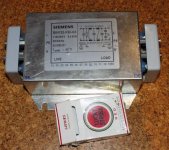
and I´m sure Your memory is better than mine (mine almost can`t be worse) Some filtering is exactly what I plan to do:
Attachments
Hi,
Thank you Siemens for the education I was fortununate to enjoy....in Munich...
Ironish oder nur komisch?
Gruesst die,
Some filtering is exactly what I plan to do:
Thank you Siemens for the education I was fortununate to enjoy....in Munich...
Ironish oder nur komisch?
Gruesst die,
- Status
- This old topic is closed. If you want to reopen this topic, contact a moderator using the "Report Post" button.
- Home
- Amplifiers
- Tubes / Valves
- "Balanced power"