The tranny I ordered is calculated for 50VA on the heater side, which means by doubling the tubes I am on the limit. the big tubes will pull 2.5A,
2.5A for each 6AS7G, plus 0.3A the other tube. 50VA is barely enough for one tube. It's a 2x9v, 50VA, that means 2.77A full wave. A quick simulation shows that for 2.8A DC you will draw 3.2A RMS from the transformer.
The ripple current can reach 4 times the DC current. You will have spikes of 9 amperes, which saturate and heat up the transformer, and radiate into neighboring circuits, with only one tube.
No way you can power both 6AS7Gs with this transformer.
SMPS 6.3v 10A module: http://www.ebay.fr/itm/BLOC-DE-CHAUFFAGE-6-3-V-10-A-REGULE-AMPLI-A-TUBES-/261065970167
4A: http://www.ebay.fr/itm/BLOC-DE-CHAUFFAGE-6-3-V-4-A-REGULE-TUBES-/261065991778
edit: the links are not working. Search for "BLOC DE CHAUFFAGE 6,3 V- 10 A REGULE POUR AMPLI A TUBES"
4A: http://www.ebay.fr/itm/BLOC-DE-CHAUFFAGE-6-3-V-4-A-REGULE-TUBES-/261065991778
edit: the links are not working. Search for "BLOC DE CHAUFFAGE 6,3 V- 10 A REGULE POUR AMPLI A TUBES"
Last edited:
Hi,
Previously I suggested to heat the tubes using AC thinking these were 6.3 VAC sec. windings.
Even then it's too close to the limit to work comfortably for a single channel.
I usually pick heater xformers twice the VA rating I actually need, it's safer and leaves margin for experimenting with different tubes, etc.
Ciao,")
2.5A for each 6AS7G, plus 0.3A the other tube. 50VA is barely enough for one tube. It's a 2x9v, 50VA, that means 2.77A full wave.
Previously I suggested to heat the tubes using AC thinking these were 6.3 VAC sec. windings.
Even then it's too close to the limit to work comfortably for a single channel.
I usually pick heater xformers twice the VA rating I actually need, it's safer and leaves margin for experimenting with different tubes, etc.
Ciao,
I usually pick heater xformers twice the VA rating I actually need,
Me too.
These are the correct links to the SMPS modules, 10A and 4A:
http://www.ebay.fr/itm/261065970167
http://www.ebay.fr/itm/261065991778
Last edited:
Thanks guys. So I will keep the toroidal one for the B+ and the filament of the ecc88 tubes. Plus I will add a solution (either tranny or the module mentioned by Vincent), for the heater of the big tubes. Which means the heater and the B+ of the big tubes are not coming from the same transformer which is good according to prior posts
Regards
Christoph
Regards
Christoph
Hi,
Yes indeed, it avoids coupling to the B+ windings.
You mean you're still going to build the one with the ECC88 at the input?
Not sure you're going to like it but I avoid toroidal power xformers like the plague for audio designs.
Good xformer building, just like tube building, is becoming a lost art....
I could point to some good ones if you like.
You'd fall off your chair if you'd see the size of the one for my OTL amps.
Quiet as a church mouse though, nu buzzing and no heat whatsoever.
It's an important factor that's often overlooked.
Ciao,
P.S. Don't listen to me or you'll end up with a headphone amp with a price ticket worthy of a hand built Japanese amp.
Which means the heater and the B+ of the big tubes are not coming from the same transformer which is good according to prior posts
Yes indeed, it avoids coupling to the B+ windings.
So I will keep the toroidal one for the B+ and the filament of the ecc88 tubes
You mean you're still going to build the one with the ECC88 at the input?
Not sure you're going to like it but I avoid toroidal power xformers like the plague for audio designs.
Good xformer building, just like tube building, is becoming a lost art....
I could point to some good ones if you like.
You'd fall off your chair if you'd see the size of the one for my OTL amps.
Quiet as a church mouse though, nu buzzing and no heat whatsoever.
It's an important factor that's often overlooked.
Ciao,
P.S. Don't listen to me or you'll end up with a headphone amp with a price ticket worthy of a hand built Japanese amp.
Hope that this is a worthwhile hint :
This here holds another example of a OTL 6080 headphone amp:
http://www.vacuumtubevalley.com/Magazines/VTV11a.pdf
Page 24 and following pages.
Greez
Siggi
This here holds another example of a OTL 6080 headphone amp:
http://www.vacuumtubevalley.com/Magazines/VTV11a.pdf
Page 24 and following pages.
Greez
Siggi
Frank, no I am building after your design. Just a pity to change the ecc88 to 6sn7 (just optical reasons). I have still the ecc88 in the schematics but need to change that.
The transformer should be of a nice quality. not top level like nagra, but good stuff. By the way I work for nagra, but not in the Audio world
P.S. The headphone amp is for office use, so I will not push it to the max. But the next project is in the pipeline. As we worked for a customer in Taipeh, my colleague brought me some nice transformers from James for a future (still 2014) project. In my mind are KT88 tubes as I like them a lot, or 300B, not sure yet.
The transformer should be of a nice quality. not top level like nagra, but good stuff
. By the way I work for nagra, but not in the Audio worldP.S. The headphone amp is for office use, so I will not push it to the max. But the next project is in the pipeline. As we worked for a customer in Taipeh, my colleague brought me some nice transformers from James for a future (still 2014) project. In my mind are KT88 tubes as I like them a lot, or 300B, not sure yet.
I am afraid you cannot obtain exactly 150v B+, MosFET stabilized, with the 115v-0-115v transformer. After rectification you will get around 150v raw DC, but you need to have *at least* 10 volts over the mosfet (and preferably 20v or more), to insure good performance, low parasitic capacitance, low output impedance, etc.
Also, the two WCFs will draw serious current (I guess 80-100mA each channel), are you sure your transformer can supply that without overheating?
Also, the two WCFs will draw serious current (I guess 80-100mA each channel), are you sure your transformer can supply that without overheating?
If just for the looking and you want a noval similar to 6sn7 io can use 6cg7Just a pity to change the ecc88 to 6sn7
Ciao Tesla88
you are right. Looks ugly and the 4 octal tubes on that small amp are kind of dis-proportioned. My initial idea was much prettier and clean with the shielded tranny and the 2 tubes.
Furthermore the tranny I ordered was expensive and will be too small for the 4 tubes.
So maybe I go back to the initial design and modify the power supply to more easy with a choke....
thanks and greetings to italy
Chris
you are right. Looks ugly
and the 4 octal tubes on that small amp are kind of dis-proportioned. My initial idea was much prettier and clean with the shielded tranny and the 2 tubes.Furthermore the tranny I ordered was expensive and will be too small for the 4 tubes.
So maybe I go back to the initial design and modify the power supply to more easy with a choke....
thanks and greetings to italy
Chris
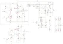
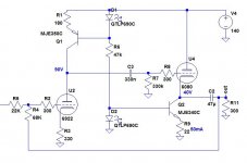
So either 160Vdc/130mA or 320Vdc/80mA. If you insist on using the 6080, we're stuck with the first option.
Let's try to use what you have. The ecc88 has too much gain. We can use some to add feedback and linearize things a bit. The 6080 doesn't have much breathing room on 140Vdc... let's ac-couple the stage and add some CCS. With your transformer and those tubes, I don't think you could do much better than this. And I'm gonna get crucified for suggesting that much sand.
Btw, I think there's a way to use your current transformer for heaters too if you use a lm2596t DC-DC converter. The to-220 version (not the smd one!) will do 3A if heatsinked (there are boards for cheap on ebay). Its efficiency gets (a bit) better as voltage goes up, so it would better to use your secondary windings with a bridge rectifier to get 25Vdc before stepping down. And you might want to put a big common mode choke after the converter.
Attachments
Last edited:
And I'm gonna get crucified for suggesting that much sand.
Actually, I might built your schematic's amp if I needed a new headphone amp. Feedback might be a good thing with low impedance cans.
Hi,
Chris, with that xformer you'd better stick to the original ECC88 circuit.
You can always build the other one later on and then we'll do it properly instead of trying to shoe horn existing components into a service they were not designed for.
Ciao,
P.S: Been reading this for most of the night:
Vacuum Tube Home Headphone Amplifier Reviews | InnerFidelity
Incredible stuff.
115-0-115v with 30VA
9-0-9V with 50VA
Best
Chris
Chris, with that xformer you'd better stick to the original ECC88 circuit.
You can always build the other one later on and then we'll do it properly instead of trying to shoe horn existing components into a service they were not designed for.
Ciao,
P.S: Been reading this for most of the night:
Vacuum Tube Home Headphone Amplifier Reviews | InnerFidelity
Incredible stuff.
Frank, probably you are right. Better to concentrate on my "bigger" SE KT88 project later this year where I would like to take less compromises (and there I will ask first before buying parts. Getting some help of you there would be highly appreciated
Ben, thanks a lot for your simplistic design. Looks interesting. you don't have schematics for the the power supply by hazard ?
The solution with the 2956 switching regulator sounds interesting and indeed there are many cheap modules on ebay, but all of them with SMD 2956 versions. But there are not many parts, and as already stated, I have lot's of spare time in the office to make a small pcb for the to-220 version with a heat sink.
So instead of reverting back to an old design I have a new alternative, great.
I really appreciate all your inputs on this forum, great stuff. What I learned is for my next amp I will really start very early a discussion here.
Best regards
Christoph
Ben, thanks a lot for your simplistic design. Looks interesting. you don't have schematics for the the power supply by hazard ?
The solution with the 2956 switching regulator sounds interesting and indeed there are many cheap modules on ebay, but all of them with SMD 2956 versions. But there are not many parts, and as already stated, I have lot's of spare time in the office to make a small pcb for the to-220 version with a heat sink.
I'm quite fond of this simple reg by Elvee . I'd keep your psu as it is but replace the zener follower by one of those, set at 135Vdc.
As for the 2956t, I've found one board on ebay . The TI datasheet for the lm2596s is very detailed if you intend to design your own board on the other hand.
- Status
- This old topic is closed. If you want to reopen this topic, contact a moderator using the "Report Post" button.
- Home
- Amplifiers
- Tubes / Valves
- New OTL headphone project with EC88 and 6080