I'm quite fond of this simple reg by Elvee . I'd keep your psu as it is but replace the zener follower by one of those, set at 135Vdc.
I have tried this kind of regulators in headphone amps and I do not like their sound.
I prefer a simple CCS+resistor voltage reference with a mosfet follower, with no feedback. Like the original schematic in this thread, but with a resistor instead of the zener string.
.
Hi Vincent. How would this resistor (replacing the three Zeners be calculated?
Thanks and regards
Christoph
I prefer a simple CCS+resistor voltage reference with a mosfet follower, with no feedback. Like the original schematic in this thread, but with a resistor instead of the zener string
Hi Vincent. How would this resistor (replacing the three Zeners be calculated?
Thanks and regards
Christoph
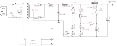
Here is the modified schematic.
R14 and R15 set the current through the diodes. 160v/43K = 3.7mA.
The voltage divider R14-R15-C10 can be used to reference the heaters at a higher potential, which is recommended. If you don't want it, replace with one 47K 1W resistor.
D3,D4, R10 and Q1 form a constant current source.
Vf of one 1N4148 at 4mA is between 0.6 and 0.7V, let's say 0.65v.
Vbe of MPSA92 is also around 0.65V.
The output current is 2*Vf-Vbe / R10 = 0.00116mA
This current will generate a fixed voltage over R11 + RT1. V = R * I
To get 153v on the gate of the mosfet, R needs to be 131.815K. RT is a multiturn ceramic trimmer used to adjust Vout (can be 50-100k). Output voltage will drift a little when components heat up, so adjust again after 30 mins or so.
R13 and C3 filter and make the voltage rise slowly (5 seconds).
DZ1 is for mosfet protection. Watch out for ESD while manipulating the mosfet. I would also use a small heatsink.
R2 must be soldered as close to mosfet's body as possible.
C2 - I would use a film cap of at least 22µ - 47µ here instead.
C1 - the same. If there is no place for large film caps, at least bypass the electrolytics with at least 2µ2 film.
edit - and make sure you have at least 10 v over the mosfet.
Attachments
Last edited:
Hi Vincent
Thank you very much for your schematics. I appreciate your help a lot.
In the mean time I received the 10A smps from France, which is a very nice device. But as 10A are over the top, I will keep that power supply for a future project.
Not sure if I buy the 4A smps or I just use the simple power supply using the TO-3 LM-323. So in the updated schematics there is still the old and simple linear heater supply. Will see.
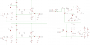
The schematics changed now to Benoîts design for 6922/6080 tubes and is attached to this post.
Best regards, I really appreciate your help.
Christoph
Thank you very much for your schematics. I appreciate your help a lot.
In the mean time I received the 10A smps from France, which is a very nice device. But as 10A are over the top, I will keep that power supply for a future project.
Not sure if I buy the 4A smps or I just use the simple power supply using the TO-3 LM-323. So in the updated schematics there is still the old and simple linear heater supply. Will see.
The schematics changed now to Benoîts design for 6922/6080 tubes and is attached to this post.
Best regards, I really appreciate your help.
Christoph
Attachments
Hi,
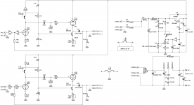
I find it regrettable to AC couple the two stages (C3). Any extra capacitor in the signal path means less transparency, and, for headphone amps, that is important.
I suggest you drop C3/R7, make R1 a 1K cermet trimmer, and so you will be able to adjust the biasing of the CF (adjust to have around 90v at V1 grid/V2 plate).
IMHO, here a ECC88 would be better than 6922.
You can also use 6CG7 or 12BH7A.
C3 can be a very good quality cap, thanks to the small value. Considering you have a big cap at the output anyway, its impact will be absolutely insignificant.
Thanks to C3 we can operate the tubes at better operating points and that is more important for good sound than one more cap. Without it, you only have 40V across the output tube.
*shrugs* that's pretty easy to test anyway. Just prepare a pcb with c3-R7 positions and a trimmer for R1 and test it with and without. Just make the heatsink on T2 much bigger since it will dissipate 5W rather than 2W if dc-coupled.
Considering the voltage involved, any tube of the E88CC, ECC88, 6922, 6DJ8 family can be used for the input. Differences in brands are likely to be just as significant than differences in type.
I find it regrettable to AC couple the two stages (C3). Any extra capacitor in the signal path means less transparency, and, for headphone amps, that is important.
Hi
I agree, and I will leave this open to hearing tests. And to change this it is easy on the PCB board. Thanks for the hint with R1 which is already implemented.
Off-Topic:
By the way, question to Vincent: Would this kind of power supply also make sense for a 420V B+ (for a KT88 amp) ? instead of 5AR4 rectifier tubes, some caps and two inductances ? for my second project...
Cdt,
Christoph
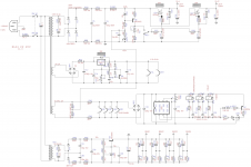
I have recently done a EL84 PP with this kind of stabilized PSU. It works and sounds good, has low, constant impedance and doesn't sag under full load.
It can be done for a KT88 too. The left and right channel supplies have to be separated. The mosfets need big heatsinks (calculate the power transformer to have 20-30v across the mosfet).
After each B+ PSU there should be a film/oil capacitor of 47..100µ, close to the output transformer and tubes (motor run caps are cheap and good).
It doesn't need chokes or lots of filtering before the stabilizer, a CRC with lowish R is enough.
Attachments
I agree with Ben, AC can be used for the heaters, but for the same price as a transformer you can buy the 4A SMPS which has soft start and stable 6.3v, regardless of the mains voltage (which fluctuates).
I recommended ECC88 because I think it sounds a little better than E88CC and it has anti-microphonic internal structure.
Russian 6N23P-EV are also very good.
I think I like 6CG7 even better... well, build the amp, and then you'll do tube rolling (it's easy with the CCS loaded first stage, just adjust the current and you can use lots of different tubes).
Post 51....
Sorry, but, IMO, tube rectifier and iron chocks will do better work for HV section, than all these "grapes", that will kill dynamics and speed of energy from PS in hard and strong moments of sounds....Sorry, I tried and forgot about SS years ago and I don't want to remember ... this is my opinion...I have recently done a EL84 PP with this kind of stabilized PSU. It works and sounds good, has low, constant impedance and doesn't sag under full load.
It can be done for a KT88 too. The left and right channel supplies have to be separated. The mosfets need big heatsinks (calculate the power transformer to have 20-30v across the mosfet).
After each B+ PSU there should be a film/oil capacitor of 47..100µ, close to the output transformer and tubes (motor run caps are cheap and good).
It doesn't need chokes or lots of filtering before the stabilizer, a CRC with lowish R is enough.
Last edited:
Hi,
+1
And if you must use regulated HT supplies, regulate everything and do it with valves.
It may not measure better but it sure does sound better (IMHO)
Whenever I hear one of these over designed SS regulated PSU I feel it sounds "caged in".
Ciao,")
Sorry, but, IMO, tube rectifier and iron chocks will do better work for HV section, than all these "grapes", that will kill dynamics and speed of energy from PS in hard and strong moments of sounds....
+1
And if you must use regulated HT supplies, regulate everything and do it with valves.
It may not measure better but it sure does sound better (IMHO)
Whenever I hear one of these over designed SS regulated PSU I feel it sounds "caged in".
Ciao,
And if you must use regulated HT supplies, regulate everything and do it with valves.
In my experiments, regulators (excepting shunt) killed the musicality and sounded lifeless. This is *not* a regulator.
Its output impedance is lower than a CLC, and, in my opinion, it sounds very dynamic. Of course, a PSU using good quality, expensive chokes, is also excellent...
In output of PS You have +310 V.There is simply not enough voltage headroom here to play with neither tube rectifiers nor tube regulators.
With rect. tube /without 10 and 20 ohms/ and after chock /about 40-60 ohm/, You will have -
270 multiply to 1.1 or 1.15 = about 300-310 V, that is aprox. the same. First el. cap must be no more 47 uF!
- Status
- This old topic is closed. If you want to reopen this topic, contact a moderator using the "Report Post" button.
- Home
- Amplifiers
- Tubes / Valves
- New OTL headphone project with EC88 and 6080