Hi H.New Year to all......re Gordon Rankin's article;
the best I can do is this website:
Sound Practices Index
... Hiroyasu Kondo A Single 807 Amp -- Gordon Rankin ... Brook Amplifiers Meet the Tube: The Trusty 807 Understanding Output ... Joe Roberts Building SE Amp Kits -- Seth ...
https://secure32.softcomca.com/southernelectricaudio_com/bac...
Apparently the issue 9 is out of print......I cannot go deeper with system crashing.
rich
Hi,
You could use a series regulator but I really don't see the need.
Here's the shunt reg as per Gordon rankin:
The 450VDC B+ is derived from a 350-CT-350 175mA xformer feeding into a 5AR4 rectifier, output goes to a 50µF/500V cap followed by a 5H 150mA choke and finally into another 50µF/500V cap.
Cheers,")
i have one Philips PCL82 here that i'd like to use as regulator. can you point me to the right place?
You could use a series regulator but I really don't see the need.
Here's the shunt reg as per Gordon rankin:
The 450VDC B+ is derived from a 350-CT-350 175mA xformer feeding into a 5AR4 rectifier, output goes to a 50µF/500V cap followed by a 5H 150mA choke and finally into another 50µF/500V cap.
Cheers,
Attachments
hi folks,
i think i had it sorted out...
i hooked it up to my 16-years old BOSE 301 Continental and the sound is so nice, no distortion even though i reckon this speaker is lowish in sensitivity at around 86dB. i thought i was hallucinating, i'm using a DACT attenuator and i cranked up the volume to maximum and i still don't hear the nasty distortion as before. so i hooked up the amp to a pair of Monitor Audio B2 speakers. still, the sound is clear.
it has a character of its own, very likeable. the midrange is surprisingly captivating and has a bottom end that is convincing even though i'm using just a Hammond 125ESE.
i don't have a way to measure output power though.
i believe there are more adjustments necessary to squeeze more from this tube as i'm operating on 44.5mA and i'd like to go up to 50mA.
tomorrow i will hook it up to my main speakers, a pair of Infinity Kappa 200.
i would like to thank all those who spent their time sharing their experience and knowledge in this thread.
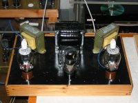
i would like to acknowledge full credit to Gabe for the 12AU7 operating points, which were used in the prototype, pictured below.
i think i had it sorted out...
i hooked it up to my 16-years old BOSE 301 Continental and the sound is so nice, no distortion even though i reckon this speaker is lowish in sensitivity at around 86dB. i thought i was hallucinating, i'm using a DACT attenuator and i cranked up the volume to maximum and i still don't hear the nasty distortion as before. so i hooked up the amp to a pair of Monitor Audio B2 speakers. still, the sound is clear.
it has a character of its own, very likeable. the midrange is surprisingly captivating and has a bottom end that is convincing even though i'm using just a Hammond 125ESE.
i don't have a way to measure output power though.
i believe there are more adjustments necessary to squeeze more from this tube as i'm operating on 44.5mA and i'd like to go up to 50mA.
tomorrow i will hook it up to my main speakers, a pair of Infinity Kappa 200.
i would like to thank all those who spent their time sharing their experience and knowledge in this thread.
i would like to acknowledge full credit to Gabe for the 12AU7 operating points, which were used in the prototype, pictured below.
Attachments
here is the updated schematic.
a friend who will be dropping off the 0C3 and 0D3 was not able to come by so i went ahead and got me some Zener diodes - 1 x 51V, 2 x 100V all 1W. i also grabbed some 0.1uF 630V Mylar capacitors and paralleled it with the Zener diodes, as can be seen in the schematic.
i am still wondering why my Screen voltage across the series of Zener diodes is at 261V though. could be the caps?
the voltage readings were the actual voltages that was measured tonight, taken about 45 minutes of listening to the amplifier. i was completely amazed at the balance of voltages between the two channels now. prior to the modifications, one channel was off by as much as 3V on the cathode voltage. now, one is 17.8 and the other is 17.6 807 cathode to ground.
any other suggestions about this amplifier is most welcome.
Attachments
I'm not a high voltage zener fan....noisy, and considerable voltage drift with temperature. I tried zeners in my tube amp and soon abandoned them.....
Go by the stabiliser circuit..... Frank posted.... using OA'S etc......great blue glow and discussion piece. Remember, tempting may it be; don't shunt a stabiliser tube with a medium uF capacitor or it will oscillate.
rich
Go by the stabiliser circuit..... Frank posted.... using OA'S etc......great blue glow and discussion piece. Remember, tempting may it be; don't shunt a stabiliser tube with a medium uF capacitor or it will oscillate.
rich
arnoldc said:hi folks,
i would like to acknowledge full credit to Gabe for the 12AU7 operating points, which were used in the prototype, pictured below.
Gee, you are making me blush!! Stop it!

As for the 125ESE transformers, they do sound OK. The 300 B makes them go down to 40 Hz!
But when you get a pair of the Hammond 1627SE's look out! Those bad boys sound terrific!
See, you do not sound disappointed. I am sure you are delighted with all your good, hard work.
Happy listening!
Gabe
arnoldc
Very nice job! Your amp looks terrific. Glad to hear that you have her running. They do have a sound all their own I think. I fired up mine on the bench today and listened to some music. I have the grid supplied from one source and the plate voltage from another. Triode sounded like crap when I started pushing it.
I ended up using 2) 6SN7's for the front end and I still can't get more than about 3watts RMS into a 8ohm load with a 1K sine wave. I have plenty of drive voltage to the 807 so I am scratching my head on this.
I don't know how people get 12watts RMS out of one of these.
J
hi rich, at the end of the day the amp will have VR tubes for regulation. it is just that i wanted to find out if the circuit is really crap, which turned out not so.richwalters said:I'm not a high voltage zener fan....noisy, and considerable voltage drift with temperature. I tried zeners in my tube amp and soon abandoned them.....
Go by the stabiliser circuit..... Frank posted.... using OA'S etc......great blue glow and discussion piece. Remember, tempting may it be; don't shunt a stabiliser tube with a medium uF capacitor or it will oscillate.
rich
hi gabe, i originally wanted to use Tango U-808 for this, but i changed my mind and will stick to the Hammond and probably use 1628SE for a 5K primary. bad boys - and big too!Gabevee said:
As for the 125ESE transformers, they do sound OK. The 300 B makes them go down to 40 Hz!
But when you get a pair of the Hammond 1627SE's look out! Those bad boys sound terrific!
Happy listening!
Gabe
hi joe, i can't wait to measure power output on mine, which i have no idea yet. however, it seemed to be louder than my JE Labs SRPP 2A3 but not louder than my JE Labs 300B DX - in all cases no active preamp was used just a passive attenuator with a DACT in it.burnedfingers said:I ended up using 2) 6SN7's for the front end and I still can't get more than about 3watts RMS into a 8ohm load with a 1K sine wave. I have plenty of drive voltage to the 807 so I am scratching my head on this.
I don't know how people get 12watts RMS out of one of these.
J
Hello,
New guy here...
Just thought I'd toss my opinion into the mix...
A few things strike me right away when reading this thread.
First, the issue of output power. This is a Class A amp and. as such, efficiency of 35 - 40% is the best you're ever going to hope for. Class A is, by definition, grossly inefficient. So, if you have a B+ of 350v and an idle current of 40mA, the tube is dissipating, at idle, 14 watts (not counting the screen.) At Class A, you're never going to get more than around 4 watts this way. And distortion will be high, as the tube is just running too cold. An 807 is rated at 25 watts anode dissipation. Use it! 14 watts at idle is even cold for Class AB.
Using your updated schematic, if you simply change the cathode resistor (on the 807) to 220R, you should get around 8 watts before clipping with a 5K load. If you want more, you'll have to bump up the B+, but you'll soon reach a point of diminishing returns.
Next, the bypass cap on the 807 cathode resistor is just too small. You'll see a low freq roll-off much too early with the 47u. Bump it up to around 250u and you'll be down less than 2db at 20Hz.
The rest should work fine, but I, personally, would rather use a seperate screen supply or, at least, a voltage divider to derive the screen voltage. And I'd add a healthy filter cap at that node, then pull my driver B+ from there, rather than from the anode node.
Speaking of the power supply, along with the increased anode current comes, unfortunately, increased hum. The major problem with any SE tube amp. Because all of the anode current is *standing* in the primary of the OPT any ripple will pass through to the speakers. If you increase the idle current, you may well find that you need more filtering in the power supply. Your CLC section is good, but you may need to increase the 100u.
About the OPT. Those little Hammonds are not going to cut it if you make these changes which, IMO, you really need to make in order to really enjoy the 807s you've chosen to use. Though I've not personally used those trannies, I can tell you just by the physical size that you'll run into trouble on two fronts. The increased idle current is going to move the cores real close to magnetic saturation. Once the core is saturated, you're out of business. The 220R cathode resistor will have the 807 drawing around 60 ma at idle, and I'm farly sure that small Hammond core will be near saturation at that level. At any rate, you won't be able to send much program through the transformer before it saturates. The other problem, which is really the same problem, is the increase in size of the bypass cap on the 807 cathode resistor. This will extend the low freq range which will... tend to saturate the core of the OPT. And OPT saturation is a particularly ugly form of distortion, IMO.
As a cure, I can suggest two options.
I've heard great things about, but have not personally tried, the one electron SE OPT. It certainly looks good on paper, and I've spoken with people who have great success with them.
If it were my amp, I'd use the Mercury Magnetics AXIOM-SE-5K. I have used this one, and it is awesome.
Unfortunately, both of these transformer are quite large, and I doubt either of them would actually fit on your chassis, but I'm just going by the photo you posted.
Anyway, sorry for the intrusion, hope it helps at least a little...
hi gary,
a most welcome "intrusion!"
i will certainly do these as my next steps moving forward, and i'll post the results here.
i checked the mercury magnetics web site and their prices are reasonable, those transformers sure look BIG!
the chassis is just a prototype so i wouldn't mind having bigger iron.
thank you very much on your recommendations!!
Another SE807
Here's another SE807 project :
Triodedick 807
and the complete transformerset :
AE-Europe
Jim
Here's another SE807 project :
Triodedick 807
and the complete transformerset :
AE-Europe
Jim
The shunt regulated screen supply with the VR tubes works great!
I junked out an old organ amp today it lent its chassis, transformer, and filter caps to the project. The screen supply stayed at 250-251 volts and I set the B+ at about 430. I had the capability to hit 454 volts but didn't like the sound of the amp at the higher voltage.
I junked out an old organ amp today
it lent its chassis, transformer, and filter caps to the project. The screen supply stayed at 250-251 volts and I set the B+ at about 430. I had the capability to hit 454 volts but didn't like the sound of the amp at the higher voltage. arnoldc
Quote:
hey joe, how much power do you get at 434V B+ ?
Well. I got a tad over 11watts into an 8ohm load with a 1K sine wave before it started to clip. It seems the VR circuit made a difference. I also used a larger transformer that I pulled from an old 6L6 PP amp.
I believe that I will lower the B+ feed to the plates to 400V and see what is sounds like there. It looks like the amp likes to see around 60mA to sound good. Surprising enough there is even some bass. The midrange detail is very good, somewhat scary when your not used to it.
J
Here's the shunt reg as per Gordon rankin:
The shunt regulated screen supply with the VR tubes works great!
Does the screen grid on an 807 really draw enough current for VR tubes to be effective? I hadn't thought so and am wondering if this improvement is psychological.
John
So true! My friend who heard it using a Bob Brines designed floorstander with Fostex FE167 commented about how that midrange showed its character.burnedfingers said:The midrange detail is very good, somewhat scary when your not used to it.
J [/B]
I'd be making mine 400V too... and my itchy fingers are telling me to use 5842...

Quote:
Does the screen grid on an 807 really draw enough current for VR tubes to be effective? I hadn't thought so and am wondering if this improvement is psychological.
Well John the screens draw 5mA at idle and upwards of 14mA when the amp is pushed. As far as it being psychological, what can I say? Before the VR's I used a 10K resistor to a B+ supply of 250volts and managed to get less than 4 watts out of it. When you figure that I get 11 watts out now something has made a difference. You be the judge.
Quote:
I'd be making mine 400V too... and my itchy fingers are telling me to use 5842...
What the heck, give it a try. Save your operating points of what your using now for future reference. Let us know how it turns out.
I ended up using a 6SL7 and a 6SN7 for the front end. It puts out a sh*t load of drive voltage.
J
Nothing exceeds like excess.
- Status
- This old topic is closed. If you want to reopen this topic, contact a moderator using the "Report Post" button.
- Home
- Amplifiers
- Tubes / Valves
- Distortion in 807 amplifier - please advise