This website explains it in details (go to part3) and provides an excell spreadsheet. It's also quite easy to sim in spice if you have sufficient data about your transformer.
Thank you!
I think I'll go work on it for a while
")
Do you guys do anything to discharge the big parafeed cap? I've gotten a nasty, unexpected shock from mine, a day after powering it off.
I would think that it would discharge through the tubes after the B+ was turned off but the cathodes were still hot enough to conduct. I don't know what your circuit looks like so it's hard to say.
Good point. It's on my workbench, so this was probably an odd circumstance. I'll take that off my list of concerns.
Thanks
Also, you can substantially lower the output impedance for your amp by taking the feedback from the transformer secondary rather than the primary. It's up to you of course. I would never tell you what to do. I'm doing that with the one I'm building.
What you say is true but I am not sure if it is of any real benefit when driving headphones, even 32 ohm ones.
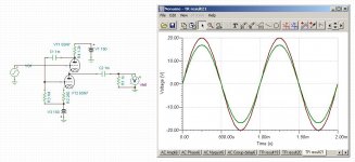
Just for fun, here's what can be done with a 6SN7 White Follower. Twenty volts p-p driving 1k ohm. Visual clipping occurs at over 35 V p-p input, which is about 2.3% THD and works out to 21 V rms into 1 k ohm. (441 mWatts) I think that's pretty dang good!
I have done many sims of White followers.Unfortunately when built and measured they are not nearly as good as the sim suggests.
Cheers
Ian
P.S Why did you delete your post?
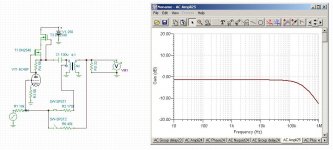
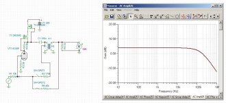
When you take the feedback from the primary side, the voltage gain of the amplifier is much more strongly affected by changes in load than if you take it from the secondary of the transformer.
As you can see from the two circuits the gain goes way down with the feedback taken from the primary side of the transformer. The feedback was set @ 10 dB for each path with a 100k ohm load. Then the load was changed to 32 ohms. This is the result.
If you adjust the resistors in the feedback paths to give equal gain for the circuit when driving 32 ohms, then the distortion is about the same for either path. I guess that makes sense since the gain is the same.
Attachments
Last edited:
P.S Why did you delete your post?
Did I delete a post in this thread? I don't know if I did that. I can't remember, sorry.
Well, you can always put a high value bleed resistor in parallel with the parafeed capacitor. Something like 1M ohm.
That is probably a good idea.
I built a breadboard version of my amp with the first iteration of the transformer I wound and it measured and sounded good despite the sims with low cap values.
I need to dig out the tubes again and rus some more tests.
I missed out on a TDR at the scrap sale today. I forgot to enter a bid. No big loss as I don't really think it would be usefull at audio frequencies.
Did I delete a post in this thread? I don't know if I did that. I can't remember, sorry.
There was one with a schematic of a 6SN7 based white follower driving a 1k load that seems to have gone.
Cheers
Ian
There was one with a schematic of a 6SN7 based white follower driving a 1k load that seems to have gone.
Cheers
Ian
This one?
The 6SN7's are on the edge I believe, running at some 11mA. I have no idea how well this would work in real life, but I was trying to show that when I optimize the plate resistor for the specific load, then it's possible to really drive the White Follower hard, and it's possible for it to put out a lot of power.
Attachments
Last edited:
The preceeding stage was a 12AT7, which was DC coupled to the ECC99. Like the Earmax/Morgan Jones/OMJ topology. Sounds great! And with the ECC99's power to spare going into my 55 ohm AKG's.
EDIT: I had to be carefull with biasing the output stage. It was too easy to exceed the rated wattage of ECC99 with this topology.
EDIT2: To make things clear, I calculated an optimum load resistor of around 130 ohm, while 220 measured the best results (THD and equal signals on ECC99's grids).
EDIT3: I really should read better before posting. I connected the headphone directly to the output. No transformers whatsoever. Only a BIG coupling cap on the output. Trick was to determine the high pass with the input cap and NOT the output elco so there's never any real voltage drop across it.
Last edited:
- Status
- This old topic is closed. If you want to reopen this topic, contact a moderator using the "Report Post" button.
- Home
- Amplifiers
- Tubes / Valves
- Headphone Impedance and headphone amplifier