The question is, how to choose the screen grid voltage (and then, the current) for a voltage amplifier, taking into account I need the maximum amplification, and plate voltage swing, regardless on distortion issues.
Some time ago, I saw a page in where he author solve this question taking some points on the datasheet curves, and making the tube equation for a 6AU6 pentode, but I can't re-find it.
I don't want to make simulations, in fact I prefer to make the calculae in the usual manner, with pen and paper, and the tube I'll use is the pentode section of the 6BH11 compactron tube.
Many thanks in advance.
I think you mean this one:There is page on pentode preamp design at ampbooks, but I can't seem to access the site, may be you have better luck...
Pentode DC Operating Conditions
The question is, how to choose the screen grid voltage (and then, the current) for a voltage amplifier, taking into account I need the maximum amplification, and plate voltage swing, regardless on distortion issues.
I can only tell you that the potential of g2 reduces the number of electrons in the electron cloud, increasing the current, and thus it increases the gain.
But I can suggest you the wrong sites

http://www.diyaudio.com/forums/tubes-valves/243716-preamp-pentode-screen-voltage-gain.html
The question is, how to choose the screen grid voltage (and then, the current) for a voltage amplifier, taking into account I need the maximum amplification, and plate voltage swing, regardless on distortion issues.
Some time ago, I saw a page in where he author solve this question taking some points on the datasheet curves, and making the tube equation for a 6AU6 pentode, but I can't re-find it.
I don't want to make simulations, in fact I prefer to make the calculae in the usual manner, with pen and paper, and the tube I'll use is the pentode section of the 6BH11 compactron tube.
Many thanks in advance.
This requires a lot of trade-offs. Generally, you increase both the gain and output swing by loading the plate lightly, making a shallow loadline. The plate characteristics of the pentode section pretty much flatten out at VPK= 75V at the VGK= 0 line. You could use that, but selecting Vpk= 100V would be better.
This gives you the floor of the plate voltage swing. The ceiling would, of course, be:
VP(max)= Vo + 100 (P-2-P output voltage)
VPKq would be the value that's in between the extremes of plate voltage swing. As for the actual plate load resistor, that would be determined by how much VPP you have. Higher rail voltage allows for larger plate resistors to increase voltage gain. Reducing the Q-point plate current also allows for increased plate load resistance. That does reduce the gm, but for the most part, the increased plate resistance more than makes up for that, and you'll still get the voltage gain.
As for setting screen voltage, the lower the screen voltage, the lower the grid bias for any given plate current. You need at least enough grid bias to keep Vgk <= 0 to avoid Class A*2 operation (almost never desirable for a voltage gain stage). To pick off a screen voltage, refer to the "Transfer Characteristics". Even though these are plotted at a fixed VPK, it won't make much difference since plate current is relatively independent of VPK. If the design nominal VPK is radically different, you will probably have to make some empirical adjustments to screen and/or control grid bias values.
taking into account I need the maximum amplification, and plate voltage swing, regardless on distortion issues.
Gain and headoom both *increase* as you raise the screen voltage. But what do you mean, 'maximum amplification'? If you truly want the maximum possible gain then you need an infinite load impedance, in which case the gain will equal the mu of the pentode, which could be in the thousands. That's not a practical way to design a pentode circuit. You probably need to narrow down your requirements a bit.
Last edited:
Not quite. The slope is as you say, but the intercept will be different from a simple resistance. Put the loadline (with the calculated slope, which will be almost horizontal) through the quiescent point. You will find that the quiescent anode voltage will depend critically on exact valve parameters so this arrangement is not practical, as Merlinb says.Osvaldo de Banfield said:On the other hand, how do I make the loadlines for pentode loaded with a triode in SRPP mode? Is it the same way as normal R loaded, but using the equivalent ((µ+1)*Rk) + rp(t)) as the loadline slope?
Gain and headoom both *increase* as you raise the screen voltage. But what do you mean, 'maximum amplification'? If you truly want the maximum possible gain then you need an infinite load impedance, in which case the gain will equal the mu of the pentode, which could be in the thousands. That's not a practical way to design a pentode circuit. You probably need to narrow down your requirements a bit.
Merlin, thanks for the reply. What I want to say, is the maximum gain given a pentode previously selected, in this case will be a high gm pentode from the 6BH11 compactron: http://www.jogis-roehrenbude.de/Roehren-Geschichtliches/Compactron/6BH11/6BH11.pdf
DF96, thanks also by the suggestions.
Miles: the amp will be a DC coupled DC amplifier, in single ended mode, nothing in push pull, so unfortunately, your post doesn't apply, many thanks too.
OK, interesting page, guy. I'll read it also.
My question continues to be, how to fix or choose the screen voltage. Langford Smith (LS) says, "the lower voltage that can prevent grid current", but normally in the datasheets of the tubes, the point where grid current starts is not specified. Also, LS say that grid current starts at -1V (in general) of grid bias, but not at what screen voltage stars, and how does it varies between tubes.
My question continues to be, how to fix or choose the screen voltage. Langford Smith (LS) says, "the lower voltage that can prevent grid current", but normally in the datasheets of the tubes, the point where grid current starts is not specified. Also, LS say that grid current starts at -1V (in general) of grid bias, but not at what screen voltage stars, and how does it varies between tubes.
Merlin, thanks for the reply. What I want to say, is the maximum gain given a pentode previously selected, in this case will be a high gm pentode from the 6BH11 compactron
The answer is still the same. The maximum gain will occur with an infinite load impedance and the highest possible screen voltage (i.e. highest transconductance). But the gain will be in the thousands, and probably unusable. You need to set a more practical limit. 100? 200?
Once you have decided on the gain you want, you can then decide what output impedance you can tolerate, and how much PSU current you can spare. These things will determine the anode resistor. Once you have the anode resistor, the rest is easy.
OK, guy, thanks again.
I need the maximum amplification the tube can give, at realistic anode voltages and currents. In fact, my limit is the +B, about 275VDC. As the load for the pentode will be one of the triodes in the same tube as a SRPP, the anode circuit is not a trouble for me. My question continue to be arround the voltage and current (a given fraction of anode current?)at grid 2 (Screen) that I will need to get the maximum plate swing at maximum gain for this (or any other) pentode.
Thanks a lot for your reply.
Is it really an SRPP, or merely an active load? (Maybe people mix the two up). If it is simply an active load, or an SRPP driving a high impedance, then you can get the slope of the loadline from what you said earlier:
using the equivalent ((µ+1)*Rk) + rp(t)) as the loadline slope
In reality it won't be a straight line, but it should be close enough for gorvernment work.
You can then get the screen voltage from the mututal characteristics graph (also misleadingly called the transfer characteristics). You'll probably want the load line to go roughly through the knee of the curves.
Yes, you can assume the screen current is a constant fraction of the anode current. You can get the fraction from the datasheet example values. You don't 'choose' the screen current; you choose the screen voltage. The current is just something you're stuck with.and current (a given fraction of anode current?)at grid 2 (Screen)
Last edited:
You realise that you will hit problems of bandwidth and DC stability if you really do need 'maximum' gain? Could you actually use a gain of, say, 5000 if it meant that the output was wandering all over the place? You would need a carefully stabilised g2 and heater supply for a start.Osvaldo de Banfield said:I need the maximum amplification the tube can give
You realise that you will hit problems of bandwidth and DC stability if you really do need 'maximum' gain? Could you actually use a gain of, say, 5000 if it meant that the output was wandering all over the place? You would need a carefully stabilised g2 and heater supply for a start.
Both, stability and BW are of no care in this case, in fact, a low BW will be needed. This will be used in a DC amplifier for a very strange project (not audio) still under development, and keep in top secret by this moment.
I have lurking suspicion that the current source load represented by the upper half of the srpp will result in severe dc instability as both the pentode and the srpp are going to try and set the plate current, yet it may work since triodes in srpp usually make fairly mediocre current sources.. Were this an AC amplifier I would suggest a gyrator, but since it is not.. What I might suggest is using fixed grid bias (battery) on the SRPP with a bigger cathode resistor to get as high of an effective plate load as you can manage.
I would say the best approach might be to build a test jig and measure the transconductance for a variety of different screen voltages. (I use my utracer for just this sort of thing.)
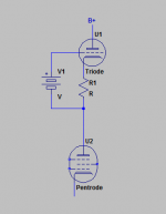
See attachment, and I expect it will be most unstable, but it should allow you to realize ridiculous gain levels with a moderately high transconductance triode if you can get it at all stable or place it inside a DC feedback loop. You can also do strange things like deliberately mismatch the currents between the srpp (set slightly higher) and shunt some of that current through a large resistance in parallel with the pentode to gnd, the pentode takes what it needs to satisfy its op point, and the rest goes to the resistor as plate voltage rises until the current delivered by the srpp is all consumed. I expect you can still get a very healthy gain this way and run at quite high plate currents to get the transconductance up. This might actually work ok if you have plenty of supply headroom.
I would say the best approach might be to build a test jig and measure the transconductance for a variety of different screen voltages. (I use my utracer for just this sort of thing.)
See attachment, and I expect it will be most unstable, but it should allow you to realize ridiculous gain levels with a moderately high transconductance triode if you can get it at all stable or place it inside a DC feedback loop. You can also do strange things like deliberately mismatch the currents between the srpp (set slightly higher) and shunt some of that current through a large resistance in parallel with the pentode to gnd, the pentode takes what it needs to satisfy its op point, and the rest goes to the resistor as plate voltage rises until the current delivered by the srpp is all consumed. I expect you can still get a very healthy gain this way and run at quite high plate currents to get the transconductance up. This might actually work ok if you have plenty of supply headroom.
Attachments
- Home
- Amplifiers
- Tubes / Valves
- Pentode's screen voltage/current