There is too high voltage on my Mullard 5-20. Without the tubes inserted, I measure 690V after the rectifier. It shold not bee that high. More like 400. On the original schematics there is two resistors between the trans. and the rectifier. The tranny is 410-0-410. What values should these resistors be? It's R26 and R27.
Thanks
Thanks
Yes........without the tubes inserted you are asking for trouble with that high voltage........YOu shouldn't test the HT unloaded...without the output tubes in sockets......If you are using the indirectly heated GZ34 rect, the warm up should be the same as for other tubes...so the HT doesn't rip off. If you are using the same rated components as per Mullard 5-20 design; C12-13 on power supply (post rect+choke) are rated for 450V.....don't stretch this with 690V, or they will <go-for-launch>.
The original quote <440V DC on centre tap of o/p tranny>;
Mains tranny should be capable of delivering 2x410V AC @180mA if the unit is to be used with FM/AM tuner. If not 2x150mA is sufficient.
<R26-R27 will depend on resistance of the transformer which for the GZ34 should be at least 110 ohms>
rich.....
More testing
Hi
I'v tested more with the tubes in place.
The tranny's are rated to 300mA. It's a stereo chassi, so it has to supply both channels. But I'm not using any tuners, so it shoul be ok.
Measured the resistanse of the tranny (with a voltmeter), and got 63 ohm's.
I tried a couple of values for the R26&27. First with 50 kohm, but the voltage only got up to 25V on the first cap. Then I tried 220 ohm. I measuerd while I switched it on. It takes a couple of seconds before the voltage raises. When it vent over 450V I switched it off. So someplace between these values should do it. 5k maybe? Any suggestions?
What rectifier are you using? If it is a "directly heated" one, like a 5U4, the voltage will surge quite high on turn on, as the rectifier warms up much faster than the output tubes. When no current is being drawn from a power supply, its voltage tends to rise.
What will happen is that the output tubes warm up and then your voltage will drop to normal levels. However, this could take 15-20 seconds, longer with EL34s. If your caps aren't rated for the high "surge" voltage, they might go pop after a while.")
Solutions:
Best solution: Use a GZ34 or similar slow-warm up tube. These take 30sec to start working, by which time the output tubes are working, and there is no high voltage surge.
Another solution is to use a "standby" switch, in the secondary centre tap of the mains transformer. This lets you control when the B+ is applied, and you can warm your tubes up before you apply the B+. I use this with diode rectifiers.
Or, if you have the caps available, put two 450V caps in series with a 220K 1W resistor across each. This (sort-of) gives you a 900V cap of half the capacitance. However, you need twice the caps.
The resistors in the schematic are probably meant to be adjusted to get your voltages spot on. Probably in the range of 100-300 ohms, 10W would be recommended. These will not fix the surge in any way.
Also be careful! Those voltages are quite nasty, make sure all caps are discharged before you work on the unit!

What will happen is that the output tubes warm up and then your voltage will drop to normal levels. However, this could take 15-20 seconds, longer with EL34s. If your caps aren't rated for the high "surge" voltage, they might go pop after a while.
Solutions:
Best solution: Use a GZ34 or similar slow-warm up tube. These take 30sec to start working, by which time the output tubes are working, and there is no high voltage surge.
Another solution is to use a "standby" switch, in the secondary centre tap of the mains transformer. This lets you control when the B+ is applied, and you can warm your tubes up before you apply the B+. I use this with diode rectifiers.
Or, if you have the caps available, put two 450V caps in series with a 220K 1W resistor across each. This (sort-of) gives you a 900V cap of half the capacitance. However, you need twice the caps.
The resistors in the schematic are probably meant to be adjusted to get your voltages spot on. Probably in the range of 100-300 ohms, 10W would be recommended. These will not fix the surge in any way.
Also be careful! Those voltages are quite nasty, make sure all caps are discharged before you work on the unit!
Hi,
The 5-20 uses a GZ34/5AR4.
Cheers,
EDIT:
Original diagram is here:
MULLARD 5-20
Best solution: Use a GZ34 or similar slow-warm up tube. These take 30sec to start working, by which time the output tubes are working, and there is no high voltage surge.
The 5-20 uses a GZ34/5AR4.
Cheers,
EDIT:
Original diagram is here:
MULLARD 5-20
Frank......got variants of two sim versions of 20W Mullard circuits both with GZ34. 1st(1960) shows 50uF 450V on DC ex rectifier and 2nd (undated) uses 8uF; all other components are same.
There is also a Philips version which has uprated 30W Pout.
I presume the version with 8uF+ 10H choke+8uF is the original Mullard as 50uF's electyt's weren't around at that time. Correct ??
However it appears the original 5-20 circuit parts list C12_C15 uses 8uF paper types then these would be rated at 500V.
Resistors R26_R27 in each rectifier anode leg are shown as 6W min rating.
rich
Hi,
I think so too.
I have another one using the GZ32 as a rectifier. Just after it, it states a B+ of 465 V so these 8µF caps should have a 500V rating at least.
So I assume the resistors need to be adjusted so we have a raw B+ of 465V.
The reason they weren't specified was that they need to be adjusted according to the xformer specs.
Not having a tuner and/or preamp taking their juices from the same supply would also make the B+ go higher by a few volts too.
Cheers,
I presume the version with 8uF+ 10H choke+8uF is the original Mullard as 50uF's electyt's weren't around at that time. Correct ??
I think so too.
I have another one using the GZ32 as a rectifier. Just after it, it states a B+ of 465 V so these 8µF caps should have a 500V rating at least.
So I assume the resistors need to be adjusted so we have a raw B+ of 465V.
The reason they weren't specified was that they need to be adjusted according to the xformer specs.
Not having a tuner and/or preamp taking their juices from the same supply would also make the B+ go higher by a few volts too.
Cheers,
Hi,
They very well could as your PS becomes more "efficient" the voltage will tend to rise.
There's also the risk that the choke will go into saturation at switch on.
What's the value of the first cap just after the rectifier?
Cheers,
Does these "unoriginal" cap values make any difference?
They very well could as your PS becomes more "efficient" the voltage will tend to rise.
There's also the risk that the choke will go into saturation at switch on.
What's the value of the first cap just after the rectifier?
Cheers,
bjørn,
The value of the resovour cap(s) C15, will have a big effect on the voltage produced.
You can reduce the value to reduce voltage.
If C12 is bigger than spec, you may be able to reduce C15 to below the specified 8uF.
The choke may buzz with small values.
You must do all the measurements with the tubes inserted. You can switch off before any overheating occurs. Keep an eye on the cathode voltage of the EL34's. If it exceeds the specified value by 10%, switch off.
It's ok
I'v tested with different values on the resistors, and found that appr. 500ohm is ok. Then there is ca. 420V after the choke. But still there is a mechanical noise (quite high) from the amp. Can not target where it's coming from. In that matter I have some questions to find out if I have done something wrong.
1. Do I need a dummyload at the output (8 ohm) when I switch the amp on? Is there any problem if I don't use any load on the output?
2. The heaters on the tranny are marked 6,3V on 1 of the leaders, and 0V on the other. I have connected both to the heater filament. Is that correct, or should the 0V go to earth, and then connect the one pole of the heater filament to eart also?
Same goes for the 5V for the rectifier.
Bjørn
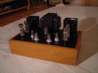
Bjørn,
Nice looking amp
If the 6.3v heater windings don't have a centre tap, it's best to make a virtual centre and ground that. You can make one by adding 2 resistors in series across 0v to 6.3v, and grounding the centre. Suitable values range from 47 ohms to 470 ohms. Of course they must be the same!
You don't have to do this to the 5v winding.
Hi,
This shouldn't be a problem for as long as you don't apply any signal to the input.
You could put a 1K resistor across the 0-8 Ohm terminals just to be on the safe side.
Cheers,
1. Do I need a dummyload at the output (8 ohm) when I switch the amp on? Is there any problem if I don't use any load on the output?
This shouldn't be a problem for as long as you don't apply any signal to the input.
You could put a 1K resistor across the 0-8 Ohm terminals just to be on the safe side.
Cheers,
Ok
I have got rid of the oscillating, and got the resistors R27 and R27 rigth. The trouble is that they are melting down. I did some calculating, and here it is:
The manual says a current use of 145mA (for the monoblocks). That means twice for the stereounit I use (290 mA). The resistors I use now is 230 ohm's. 290mA trough 230 ohm is 64V. That I also what I measure over the resistors. But this also means over 17W (U*U/R). That is strange, since the manual says 6W (monoblock)
Anyone got a clue?
Bjørn
Mullard 5-20 amp
I read your posting with much interest.
If you persuse my web page:
http://www.shermanaudio.com
You can see what I went through in order to make my 5-20 amps stable, it was similar to your posting, and some fried quads of EL34's.
The specification for the mains transformer that is given in the Mullard Book should be matched as closely as possible.
In my case I used a Hammond 278X Mains Transformer that is over-dimensioned for the application. The problem with the Mullard 5-20 amp is that the voltages must be set according to the manual's recommendation.
Assuming that the schematic has been copied exactly (all resistors and capacitors the same as the original) then one must aim for 465 Volts DC on the first capacitor after the choke (or series dropping resistor in case your design is not using a choke. In addition the series resistance of the choke (or resistor) must be 200 Ohms in order for the voltages to match.
If the mains transformer is over-dimensioned in any particular area, such as the 6.3 Volt filament section, or even the 5 Volt tube rectifier section (omit if using diodes) then the resulting voltages will be boosted and affect the amplifier's performance. All of this assumes a Mains transformer wound for 115 VAC (or 220 VAC) in the primary. The Hammond has 6 amperes @ 6.3 Volts when the 5-20 amp only needs a maximum of 3.5 to 4 amperes. This un-balanced the secondaries and caused the HV to become boosted as well. The main reason is that my mains is at 123 VAC and the Hammon's are tested at rated curent draw with 115 VAC on the primary (8 volts difference, not trivial).
Todays real world voltages will place a strain on new or vintage mains transformers that are designed (wound) for 115 or 220 VAC on the primary. Often one can measure mains as high as 124 Volts (in my country) or 230 Volts ( I measured this in Sweden 4 weeks ago). These real-world voltages can easily throw off a tube amps voltages and cause damage to some Vintage amps.
On the subject of the two rectifier resistors, the Mullard book provides a calculation method to be able to determine the proper value of these two 'voltage controlling' resistors.
The formula given on page 28 is:
Rt = Rs + n^2 Rp
Rs = The resistance of half the secondary HV winding (measure with a good ohmmeter)
Rp = The resistance of the total primary winding (same measured as above)
n = The ratio of the number of turn on half the secondary winding to the number of turns on the whole primary.
The value R of the resistance which must be added to each anode circuit to produce the necessary limiting value Rlim is:
R = Rlim - Rt
In my particular case with the Hammond 278X I calculated 120 Ohms each (10 watts each).
As a closing note, for a Stereo 5-20 amp, I would suggest a minimum HV capacity 410-0-410 @ 340 milliamps (360 milliamps is the ideal value according to the Mullard specifications 2x180ma).
Running a Stereo 5-20 with only 300 milliamps takes the HV secondary right to the limit as each channel of a stereo 5-20 amp will consume 147 to 150 milliamps quiescent. One always needs 20% move current capacity than the actual DC current draw when designing the typical tube rectified power supply. With Diodes this value can go as low as 8 to 10 margin as the voltage loss is not as great. The extra capacity allows for the amp to 'breathe' and have some damping from the power supply.
Hope this helps....
BR/
Rich
Interesting posts, here's my slant on the 5-20....
R26 and R27 on my 5-20 Mono-Blocks are installed as R=120 Ohms, 10 Watts each. The recommended value of these resistors is on page 52 of the Mullard book.
For GZ34 it says: GZ34 : 2x400 : 8 uF : 125 Ohms
I just completed a re-build of my 5-20 amps. After years of modifications and experimentation, the decision was to solder the whole amp back to the original schematic. I used a 4 section 20-20-40-40 Electrolytic Cap rated at 525 VDC. The C15=20uf, C12=20uf, C5=40uF and C4=40uF.
One could very well order some nice 600 Volt Tin Foil caps at 8uF each and make the amp just like the original. I just find the multi-section electrolytic convenient. Plus the extra uF are not an issue.
But what I have found with my particular amps and the Hammond 278X Power Transformer, this power transformer is just a bit 'over dimensioned' on the 6.3 Volt Filament section. This causes the secondary voltages to become 'boosted' as the amp's total filament draw is approximately 3.5 amps, not the 6 amps that the Hammond provides. The filaments end up settling in at about 7.4 Volts AC, over one full volt over the required value.
My tweak was not the best...., but ...I placed a power resistor in Parallel with each EL34 filament to 'load' the 6.3 volt section to it's designed center and the amplifier voltages settled down a bit more. I calculated each power resistor to draw 1.0A each, about 6 Ohms each resistor at 10 watts. Sure it heats up, but the power transformer is running better at it's rated load that without them.
The final adjustment came when I tested and lowered the mains voltage with my Variac and obtained the 465 Volts on the first capacitor. From there the voltages matched the Mullard manual 100%. The mains voltage that I need to make the amps settle down with the Hammond is about 115-117 VAC. More than this and the tubes start to draw more current than they were designed for.
I am planning to order some custom Power and Chokes for my amps, I will let you know if I do order these as buying in quantity brings the price down.
Funny how with un-regulated tube power supplies bigger is not necessarilly better.
Hope this help with R26, R27 and the voltage control issues on 5-20's.
Bye,
- Status
- This old topic is closed. If you want to reopen this topic, contact a moderator using the "Report Post" button.
- Home
- Amplifiers
- Tubes / Valves
- Resistors in power supply