You can and should touch the solder directly to the tip, place the tip directly on the joint to be soldered, touch the solder to the tip generally between the iron and the joint, flow the solder into the joint by adding more solder until the joint is covered and leave iron in place until solder has fully flowed into the joint. Remove tip and allow to cool. Joint should be shiny when cold, reheat if not, adding a bit more solder if necessary.
Google soldering technique and look at pictures of good solder joints.
http://www.aaroncake.net/electronics/solder.htm
Google soldering technique and look at pictures of good solder joints.
http://www.aaroncake.net/electronics/solder.htm
George @ tubelab has a good info on soldering--
Getting Started | Tubelab

After the part is inserted into the PC board, the leads should be slightly bent outward to prevent the part from falling out when the board is flipped
over for soldering. Do not bend the leads more than needed to keep it from falling out. Doing this will make it difficult to remove the part if it becomes necessary.

Each lead of the component is then soldered in place. The pads on this board are oversize where possible to aid in soldering.


The excess part leads should then be clipped off using diagonal cutters.
 The completed solder joint should look like this.
Getting Started | Tubelab
After the part is inserted into the PC board, the leads should be slightly bent outward to prevent the part from falling out when the board is flipped
over for soldering. Do not bend the leads more than needed to keep it from falling out. Doing this will make it difficult to remove the part if it becomes necessary.
Each lead of the component is then soldered in place. The pads on this board are oversize where possible to aid in soldering.
The excess part leads should then be clipped off using diagonal cutters.
desoldering braid works bestwhen you wet it with solder flux before using it. In fact, if you have flux, you can use some stranded wire. I use #12 stranded and liquid flux for desoldering all the time. Also, use the thinnest rosin core solder you can find. it will help prevent applying too much solder (which is also one of the problems i see in your photos).
to alot of folks, soldering is more than a functional activity but an opportuinty for artistic expression.....so sure...a lot of folks will chime about how the joints look.
it's too hard to tell if you have cold solder joints. some cautions.....be careful how much additional heat and mechanical force you apply on existing solder connections....you run the risk of having the cooper traces peel off the board.
what would I do....I would use a cooper wick with fluc to quickly draw off excess solder....then use a thin flux core solder to re-flash the joints. when they cool...cut off the excess leads....but dont leverage the cutting pliers on the board...leave some space so you dont pull the traces.
The common mistake is to use a soldering iron which is too small for the task; no point having a small bit with a very high tip temperature as this will cool down too fast on a medium sized joint with high copper content which conducts so fast that the flux doesn't do it's job. There is more to soldering science and how fluxes "wet" the joints, than one is led to believe, especially the globule and eutectic performance of differing alloys.
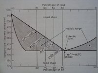
An graph extract from my metallurgy book of 1955.
Note the all important "plastic" ranges....DON'T move the joint within this range as it will become imperfect...hence the 60Sn/40Pb is eutectically pretty close to being able to instantly "freeze" after the heat is taken off, exactly what one is after on electronic joints. The other consideration is this standard 60Sn/40Pb is quite soft; for stronger joints the rarer 40Sn/60Pb is used, but with correspondingly higher heat. The catch with this grade and others either side of the graph...DON'T move the joint within it's plastic range !!
Simple when one knows how.
richy
Attachments
Last edited:
Yes that is a very important point. While I can appreciate the novelty of eutectic solder, I would not place it as a priority at all.
As Richwalters say's don't move the joint.
Now when you consider this for a second, this requires to have the parts being soldered secured so they sit still when you move the iron away. This is required regardless of the solder type.
So one has to ask, what is the goddamn rush that you need your solder to harden so quickly?
"Regular" 60/40 hardens fast enough for my uses. Soldering is one of the least time consuming activities when assembling something.
3) Snip the leads before soldering leaving about 2.5mm protruding.
All your tips are good but this one is a remarkable one. It seems the whole world solders lead wires first and then cuts the excess wire while I have learnt that the joint will be stressed mechanically and that will possibly lead to premature failure (which BTW is a proven fact).
Bravo!
As Richwalters say's don't move the joint.
I was taught in 1980 to make things mechanically secure before soldering them. If I put in a resistor I bend the legs slightly so they don't fall out when I invert the pcb.
Its the same for wires, if I use a terminal pin I always wrap the wire 180 degrees around the pin before soldering it. This makes it secure but doesn't stop it being de-soldered easily.
All your tips are good but this one is a remarkable one. It seems the whole world solders lead wires first and then cuts the excess wire while I have learnt that the joint will be stressed mechanically and that will possibly lead to premature failure (which BTW is a proven fact).
Bravo!
Thanks. That's certainly the main reason. Another is that cutting the wire first gives a 100% "clean" surface at the cut where the solder will "take" perfectly even if there is tarnishing on the main part of the lead. On my own boards I also lightly bend the wires toward the print, not sharply and perhaps to around 30 degrees. A 0.5mm lead in 1mm hole means there is a lot of solder doing the bridging, which I don't think is good.
It is OK to cut the lead after soldering if flat faced 'flush' cutters are used. Bevelled cutters could possibly stress the soldered joint.
I was involved with investigating a large number of failures of reed relay inserts way back in the late 60's. The hermetic seals were being damaged due to the shock transmitted back to the seal if the leads were trimmed with bevelled cutters. There was no problem if flat faced cutters were used with the flat face towards the reed.
Since then all my cutters are flush and not the double bevelled type.
One last thing among all the other great advice here: KEEP THE SOLDER OUT OF YOUR MOUTH! It has lead and will hurt you.
Stan
Sorry Stan,
Many of us in the 1950's had NHS dentistry algam = mercury+ antimony+ lead in our gobs....and still remains as fillings. We didn't get any say in the matter, as there was no substitute other than a rip out.
After all this time (50yrs) poking with a soldering irons and forge work hasn't effected me, and recent lead level checks, show tolerance levels way under the accepted.
The rosin flux fumes are another issue and require even more care esp those with asthmatic sensitivity. Daresay if one smokes tobacco or that white stuff, it doesn't matter, does it.
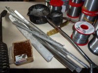
Notice; the constituent alloy percentages are stamped on the bars. There is nothing more aggravating than not knowing what one is using.
richy
Attachments
Last edited:
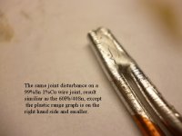
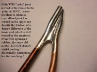
Here's a few more examples of the soldering chemistry, engineering sciences way back in 1966; all related my graph post #28;
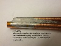
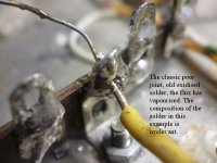
I get many mails regarding "what is the plastic range"; It is when the alloy is in a phase of neither being liquid nor solid. Too great a plastic range means that the cooling down period is protracted and, usually, the amount of heat required for correct fusing of the metals is greater. These add to the danger of a dry joint. Too small a plastic range means from transition from liquid to solid on cooling would be too rapid and a fractured bond results.
Above all; the poorly soldered over oxidised joint should be quite distinguishable from the quality ones with a smooth "volcano form" over the conductor. With veryhigh Sn solders, the "lustre" on the volcano form doesn't imply a poor joint.
Hope this helps.
richy
Attachments

I would recommend these videos from Youtube on soldering tutorials. ")
EEVblog #180 - Soldering Tutorial Part 1 - Tools - YouTube
EEVblog #183 - Soldering Tutorial Part 2 - YouTube
EEVblog #180 - Soldering Tutorial Part 1 - Tools - YouTube
EEVblog #183 - Soldering Tutorial Part 2 - YouTube
- Status
- This old topic is closed. If you want to reopen this topic, contact a moderator using the "Report Post" button.
- Home
- Amplifiers
- Tubes / Valves
- I've made an awful mess...