Right now I'm trying to design the first stage of an MM phono stage with 600R LCR RIAA compensation network. Alas, my knowledge about pentodes circuits design is wanting.
So here are few questions.
1. On Philips E810F datasheet (the only one I have for this tube), under operating characteristics, it mentions having +12.5V on the control greed. What is this voltage for? Does it really necessary, or recommended, for a phono first stage? (I've seen some schematics of this tube in a phono first stage, some schematics apply positive voltage to the greed, while other schematics don't).
2. If my memory serves me right, I remember reading somewhere that applying stabilized voltage to greed #2 reduces harmonic distortion. Is it correct? If yes, is it meaningful at such low levels?
3. Should I choose stabilized voltage for greed #2, one option is to use VR tube. VR tubes are somewhat noisy, but it's easy to filter out this noise with a capacitor parallel to the tube. What I don't know is if those tubes radiate noise to the surroundings. If this is the case, I'll definitely not use any VR tube inside a phono stage enclosure.
4. I have no clue how to locate the most linear operating point for pentode (if there is such point). To ask that question differently, according to what is it best to choose the operating point (anode voltage, greed #2 voltage and bias) of a pentode?
5. Is it necessary, or is it recommended, that greed #2 voltage will be higher than the anode voltage?
6. When the output of that first stage is loaded by a resistive (or impedance) load which is significantly lower than the anode loading resistor (via a coupling capacitor), it appears to me that the output signal of the tube will be attenuated by the ratio of the anode loading resistor to the load. Is that correct? If not, how do I calculate the attenuation of a given load?
First, have you considered the S/N issue pentode partition noise raises?
Use the plate curves to establish a rational operating point. Regulating g2 B+ at a fraction of anode B+ yields the best open loop linearity.
A 600 Ω LCR RIAA module must be associated with a 600 Ω impedance at either the I/P or the O/P, to function properly. Best performance will be obtained with 600 Ω at the I/P. How do you propose to fulfill the requirement?
1. There may be a positive voltage, but the effective potential between the grid and the cathode is negative. That's because the positive Voltage is "annihilated" with a Cathode resistor. It's all in the datasheet, you just have to look ")
Cathode resistor: 360R
Anode current: 35mA
Grid #2 current: 5mA
Thus, the voltage at the cathode: 360*(35+5) = 14,4V
This means: 12.5 - 14,4 = -1.9V effective Grid potential.
Why you do that ? The Cathode resistor provides current feedback (series derived - series applied). This stabilizes (and lowers) the transconductance and increases the input and output resistance.
2. Kinda. If the voltage @ Grid 2 is distorted, than you will get distortion. You can also the Grid 2 to lower the distortion (feedback as in Blumlein's UL). The Problem is the very unlinear current which the G2 draws at lower anode voltages. So - Yes a regulated supply is supportive.
3. Do NOT use a parallel cap considering VR tubes. You will build an oscillator. The max. value for a cap is described in the datasheet. Just a small value is allowed.
I would leave out any gas stabilizers in a phono pre. People may have different opinions here but it just makes everything more difficult. MOSFETs are so damn cheap -> just built a Maida regulator or even cheaper with TL431 (http://www.changpuak.ch/electronics/downloads/QO-408.pdf)
4. Just look at the diagrams in the datasheet. I'd suggest you look around the 35mA range.
5. Grid #2 Voltage should be lower than anode voltage.
6. For a pentode, the amplification is roughly Vu = gm*Rout
What about that ?:
Hi Eli,
Thank you.
Yes, I did.
Thank you.
Thank you, I know it must be loaded with 600 Ω at one side.
I'm considering 3 options:
1. Large anode loading resistor -> coupling capacitor -> 600 Ω LCR module -> 600 Ω resistor.
2. 600 Ω anode loading resistor -> direct coupled to 600 Ω LCR module (with high voltage capacitors inside it).
3. Step-down transformer.
Which option will give me a larger voltage gain at the output of the LCR module?
Thank you.
First, have you considered the S/N issue pentode partition noise raises?
Yes, I did.
Use the plate curves to establish a rational operating point. Regulating g2 B+ at a fraction of anode B+ yields the best open loop linearity.
Thank you.
A 600 Ω LCR RIAA module must be associated with a 600 Ω impedance at either the I/P or the O/P, to function properly. Best performance will be obtained with 600 Ω at the I/P. How do you propose to fulfill the requirement?
Thank you, I know it must be loaded with 600 Ω at one side.
I'm considering 3 options:
1. Large anode loading resistor -> coupling capacitor -> 600 Ω LCR module -> 600 Ω resistor.
2. 600 Ω anode loading resistor -> direct coupled to 600 Ω LCR module (with high voltage capacitors inside it).
3. Step-down transformer.
Which option will give me a larger voltage gain at the output of the LCR module?
Hi there,
Thank you.
What stabilizes (and lowers) the transconductance and increases the input and output resistance – the cathode bias resistor?
How does applying positive voltage to the control greed counteracts it?
Thank you.
What to look for on the anode curves? (I know how to look at triodes anode curves but I have no clue how to do it on pentodes).
Thank you.
I'm glad you brought up this schematic. I know it for a while. One thing bugs me about it: I cannot figure out how the bias works there.
Thank you.
1. There may be a positive voltage, but the effective potential between the grid and the cathode is negative. That's because the positive Voltage is "annihilated" with a Cathode resistor. It's all in the datasheet, you just have to look
Cathode resistor: 360R
Anode current: 35mA
Grid #2 current: 5mA
Thus, the voltage at the cathode: 360*(35+5) = 14,4V
This means: 12.5 - 14,4 = -1.9V effective Grid potential.
Why you do that ? The Cathode resistor provides current feedback (series derived - series applied). This stabilizes (and lowers) the transconductance and increases the input and output resistance.
What stabilizes (and lowers) the transconductance and increases the input and output resistance – the cathode bias resistor?
How does applying positive voltage to the control greed counteracts it?
2. Kinda. If the voltage @ Grid 2 is distorted, than you will get distortion. You can also the Grid 2 to lower the distortion (feedback as in Blumlein's UL). The Problem is the very unlinear current which the G2 draws at lower anode voltages. So - Yes a regulated supply is supportive.
3. Do NOT use a parallel cap considering VR tubes. You will build an oscillator. The max. value for a cap is described in the datasheet. Just a small value is allowed.
I would leave out any gas stabilizers in a phono pre. People may have different opinions here but it just makes everything more difficult. MOSFETs are so damn cheap -> just built a Maida regulator or even cheaper with TL431 (http://www.changpuak.ch/electronics/downloads/QO-408.pdf)
Thank you.
4. Just look at the diagrams in the datasheet. I'd suggest you look around the 35mA range.
What to look for on the anode curves? (I know how to look at triodes anode curves but I have no clue how to do it on pentodes).
5. Grid #2 Voltage should be lower than anode voltage.
6. For a pentode, the amplification is roughly Vu = gm*Rout
Thank you.
What about that ?:
I'm glad you brought up this schematic. I know it for a while. One thing bugs me about it: I cannot figure out how the bias works there.
6. For a pentode, the amplification is roughly Vu = gm*Rout
What is Rout in this case? Is it the anode loading resistor parallel to the load resistor?
1. On Philips E810F datasheet (the only one I have for this tube), under operating characteristics, it mentions having +12.5V on the control greed. What is this voltage for? Does it really necessary, or recommended, for a phono first stage? (I've seen some schematics of this tube in a phono first stage, some schematics apply positive voltage to the greed, while other schematics don't).
They wanted to lengthen the "tail" for some reason.
VK= 360(35E-3 + 5E-3)= 14.4V
VGK= 12.5 - 14.4= -1.9V
1.9/40E-3= 47R5
They wanted to avoid a 47R5 bias resistor. Maybe since it's easier to bypass a 360R resistance?
2. If my memory serves me right, I remember reading somewhere that applying stabilized voltage to greed #2 reduces harmonic distortion. Is it correct? If yes, is it meaningful at such low levels?
That's right. If V2K isn't stabilized, you get a sort of remote cutoff characteristic with its greater variations in gm that degrade sonic performance. Whether it makes a difference in a small signal application depends. At very low signal levels, then it's not so much of a problem. A stiff voltage divider will usually serve the purpose of stabilizing V22. Large signal pentode stages are the ones where you'll need active regulation.
3. Should I choose stabilized voltage for greed #2, one option is to use VR tube. VR tubes are somewhat noisy, but it's easy to filter out this noise with a capacitor parallel to the tube. What I don't know is if those tubes radiate noise to the surroundings. If this is the case, I'll definitely not use any VR tube inside a phono stage enclosure.
For a very low level stage like this one, it's not necessary, and not desirable from a noise PoV. Paralleling a VR tube with a capacitor, with its ballast resistor, makes an oscillator.
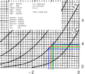
4. I have no clue how to locate the most linear operating point for pentode (if there is such point). To ask that question differently, according to what is it best to choose the operating point (anode voltage, greed #2 voltage and bias) of a pentode?
Loadlines, loadlines, loadlines: that's how hollow state design is always done. (See attached: 6CB6 loadline)
The plate xfer characteristics are usually more useful for designing audio gain stages, since the plate characteristics are frequently provided for entirely different purposes. The type you mention here says right there in its spec sheet it was designed for use as a wideband amp, not an audio amp. As such, it was intended to pull some stiff plate currents so that it could drive load capacitance, and produce useful voltage gain from smallish plate loads that improve high frequency performance.
For low distortion, you need to load the plate lightly (minimize delta-Ip) and get that screen voltage down. If you're doing pentode designs, expect that there will be a lot of empirical adjustments along the way to finalizing a design -- moreso than for doing triode based designs.
5. Is it necessary, or is it recommended, that greed #2 voltage will be higher than the anode voltage?
Not strictly necessary, but the more time the plate voltage stays above the screen voltage the better.
6. When the output of that first stage is loaded by a resistive (or impedance) load which is significantly lower than the anode loading resistor (via a coupling capacitor), it appears to me that the output signal of the tube will be attenuated by the ratio of the anode loading resistor to the load. Is that correct? If not, how do I calculate the attenuation of a given load?
Any load that the stage drives will appear in parallel with the plate load resistor. The parallel load becomes the effective plate load, and the heavier that load, the lower the stage gain:
AV= (RP(eff) || rp) X gm
I would question the suitability of a pentode for MM phono duty. Pents have an additional source of noise called partition noise in addition to the sources that plague triodes. It usually doesn't make much difference at RF, since the noise decreases with increasing frequency, but for sensitive RF designs, triodes are preferred.
You could also consider the cascode: all the gain, and much less of the CMiller of a pentode, but none of the partition noise.
Attachments
What is Rout in this case? Is it the anode loading resistor parallel to the load resistor?
Exactly. It is the sum of all the loads between cathode and anode. If there are capacitors/inductors you have to take account of different loads at different frequencies, too
Hi Miles,
Thank you.
Sorry, I don't get your reply. When a positive voltage is applied to the control grid, than a larger cathode resistor is needed, which is more difficult to bypass.
How much lightly? 100 Ω? 1KΩ?
On top of that, the lower load, the lower the gain – and I do need substantial gain in this application.
How much down? 10V on g2? 20V? 50V?
Thank you.
That pentodes are less suitable for a phono stage is the prevailing thinking. Yet, both Thorsten Loesch and Thomas Mayer (Vinylsaviour) used pentodes in that application, so I wonder.
Thank you.
They wanted to lengthen the "tail" for some reason.
VK= 360(35E-3 + 5E-3)= 14.4V
VGK= 12.5 - 14.4= -1.9V
1.9/40E-3= 47R5
They wanted to avoid a 47R5 bias resistor. Maybe since it's easier to bypass a 360R resistance?
Sorry, I don't get your reply. When a positive voltage is applied to the control grid, than a larger cathode resistor is needed, which is more difficult to bypass.
…
For low distortion, you need to load the plate lightly (minimize delta-Ip) and get that screen voltage down.
How much lightly? 100 Ω? 1KΩ?
On top of that, the lower load, the lower the gain – and I do need substantial gain in this application.
Not strictly necessary, but the more time the plate voltage stays above the screen voltage the better.
How much down? 10V on g2? 20V? 50V?
I would question the suitability of a pentode for MM phono duty. Pents have an additional source of noise called partition noise in addition to the sources that plague triodes. It usually doesn't make much difference at RF, since the noise decreases with increasing frequency, but for sensitive RF designs, triodes are preferred.
…
Thank you.
That pentodes are less suitable for a phono stage is the prevailing thinking. Yet, both Thorsten Loesch and Thomas Mayer (Vinylsaviour) used pentodes in that application, so I wonder.
Exactly. It is the sum of all the loads between cathode and anode. If there are capacitors/inductors you have to take account of different loads at different frequencies, too
Thank you.
Indeed, this is how LCR module works – it presents different load at different frequencies.
Hi there,
Thank you.
What stabilizes (and lowers) the transconductance and increases the input and output resistance – the cathode bias resistor?
How does applying positive voltage to the control greed counteracts it?
Yes, the cathode bias resistor.
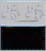
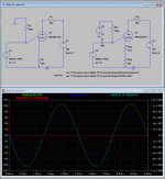
I made a little simulation to show what I mean.
The right pic in the attachments shows a 6SN7 with unbypassed cathode resistor. The left circuit has a 500R resistor and its grid at ground potential. The right has its grid @ 10V. But to achieve the same current, we have to burn ("counterburn") these 10V in turn at the cathode.
As you see, the amplification factor lowers (blue versus green graph) because of the additional feedback due to R33b.
If you bypass the Tubes, then this effect vanishes for AC signals. As you see in the right pic. But it is still present for near DC signals. We could call this some kind of adiabatic case (as in lots of physical problems).
E810F has a gigantic high transconductance. It could start to drift easily and draw more and more current. This current will be counteracted thanks to the larger cathode resistor. It is in series with the grid-cathode connection. So always when the tube starts to conduct more, it will always raise a voltage on its grid to drive it back to normal.
Considering the intended use of the E810F, I think it was always used with a unbypassed cathode resistor. The feedback prevents aging effects and keeps the transconductance constant.
Attachments
Hi,
Thank you very much.
There is nothing I see in the graphs near DC.
Indeed, though it happens with a cathode resistor of any value. I assume larger value of cathode resistor presents better counteracting of current drift. It sounds like a good idea.
By 'the intended use', do you mean RF applications?
In first stage of a phono, with extremely low audio signals, lowering the transconductance, and hence the gain, too much, doesn't sound to me like a good idea.
Possibly, in that application, it's better to use either small unbypassed cathode resistor without applying positive voltage to the control grid, or to apply positive voltage to the control grid and use larger, bypassed, cathode resistor. In the latter option, we well have better DC stability without lowering the transconductance. Is that correct?
Thank you very much.
…
If you bypass the Tubes, then this effect vanishes for AC signals. As you see in the right pic. But it is still present for near DC signals. We could call this some kind of adiabatic case (as in lots of physical problems).
There is nothing I see in the graphs near DC.
E810F has a gigantic high transconductance. It could start to drift easily and draw more and more current. This current will be counteracted thanks to the larger cathode resistor. It is in series with the grid-cathode connection. So always when the tube starts to conduct more, it will always raise a voltage on its grid to drive it back to normal.
Indeed, though it happens with a cathode resistor of any value. I assume larger value of cathode resistor presents better counteracting of current drift. It sounds like a good idea.
Considering the intended use of the E810F, I think it was always used with a unbypassed cathode resistor. The feedback prevents aging effects and keeps the transconductance constant.
By 'the intended use', do you mean RF applications?
In first stage of a phono, with extremely low audio signals, lowering the transconductance, and hence the gain, too much, doesn't sound to me like a good idea.
Possibly, in that application, it's better to use either small unbypassed cathode resistor without applying positive voltage to the control grid, or to apply positive voltage to the control grid and use larger, bypassed, cathode resistor. In the latter option, we well have better DC stability without lowering the transconductance. Is that correct?
Hi Miles,
Sorry, I don't get your reply. When a positive voltage is applied to the control grid, than a larger cathode resistor is needed, which is more difficult to bypass.
A larger cathode resistor is easier to bypass. Consider a cutoff of 20Hz:
w= 1 / RC (w= 2pi X f)
C= 1 / wR
C= 1 / (40pi X 47.5)= 167.5uF
C= 1 / (40pi X 390)= 20.4uF
You can reduce that capacitance considerably.
How much lightly? 100 Ω? 1KΩ?
On top of that, the lower load, the lower the gain – and I do need substantial gain in this application.
For small signal pentode voltage amps, 100K is considered to be the point of diminishing returns concerning distortion performance. There are designs that use larger plate resistors, and sometimes small signal pents are operated with plate currents as small as 100uA. That really isn't so good from the perspective of driving load capacitance, but it has been done.
100R would be an impossibly heavy load for any pentode. You can get away with that for wideband, BJT-based designs where you can drive up the gm almost at will. Even 1K is too stiff for pentodes.
How much down? 10V on g2? 20V? 50V?
As small as you can manage, taking into consideration the input grid swing. One general rule is that:
V2K= 0.3VPK (approx)
Of course, reducing the screen voltage requires a compensating reduction of the negative control grid voltage.
That pentodes are less suitable for a phono stage is the prevailing thinking. Yet, both Thorsten Loesch and Thomas Mayer (Vinylsaviour) used pentodes in that application, so I wonder.
There are always exceptions to every rule. Not familiar with those designs, or how their SNR compares to different designs. Given the Lo-Z nature of the equalization network you propose to use, I'd drive it with a MOSFET source follower, and not the signal preamp. You really need to buffer that, otherwise, you lose too much gain.
Hello,
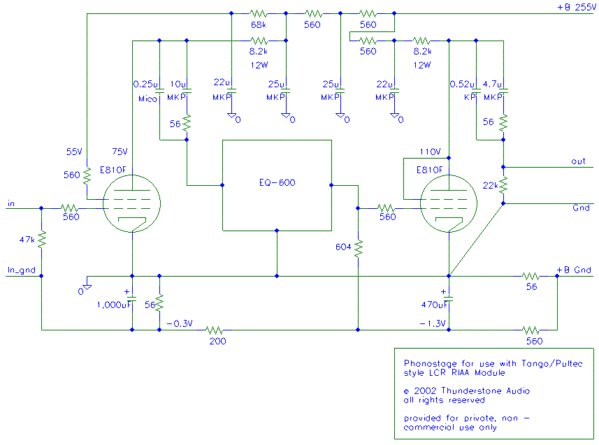
I built a 600R LCR phono stage with the E810F. I started with Thorstens design. One big problem there is the grid current with the grounded cathode of the E810F. Things are getting better over 0.6V but that doesn´t solve another big problem.
It´s a hell of a task to find matching pairs. If you have 40 tubes you might find two good pairs. But here comes the positive grid1 voltage. It stabilizes things. Instead of 2 pairs you´ve suddenly got 20 pairs.
Disadvantage is, you will need another coupling capacitor and a big cathode capacitor if you want the full gain. Gain would be quite low without it but the distortions would be very small because of the current feedback. Transconductance is not lowered by the high value cathode resistor.
Stabilizing the g2 voltage also lowers distortion. Especially if you connect the voltage stabilizer (0A2) to the cathode so that that current also flows through the cathode resistor. I couldn´t hear any more noise.
By the way, the D3a is the better choice as pentode. It has lower transconductance and therefore lower gain but linearity is much better. If I will build another phono stage I would probably do it this way: D3a pentode with positive grid1 voltage and high value cathode resistor (without capacitor) followed by a 801a with 4.5:1 interstage. 600R LCR network and the same again. Accourding to LTSpice is the output voltage about 1.2Veff with 0.006% distortions.
Best regards,
Martin
Hi Martin,
Thank you.
How did Thorsten design sound after you built it?
What was the effect (measured and/or audible) of the g1 current?
Thanks. That's certainly a practical aspect to consider.
In Thorsten's deign (E810F -> LCR -> D3a triode strapped) the overall gain is 43dB. I cannot go for lower gain, since my preamp is going to be a TVC one.
I'm not capable of designing such a phono stage myself and I'm not going to copy just any design out there. I certainly don't rely on spice results alone, without accompanying both actual measurements and listening impressions.
Thank you.
I built a 600R LCR phono stage with the E810F. I started with Thorstens design. One big problem there is the grid current with the grounded cathode of the E810F. Things are getting better over 0.6V but that doesn´t solve another big problem.
How did Thorsten design sound after you built it?
What was the effect (measured and/or audible) of the g1 current?
It´s a hell of a task to find matching pairs. If you have 40 tubes you might find two good pairs. But here comes the positive grid1 voltage. It stabilizes things. Instead of 2 pairs you´ve suddenly got 20 pairs.
Thanks. That's certainly a practical aspect to consider.
By the way, the D3a is the better choice as pentode. It has lower transconductance and therefore lower gain but linearity is much better.
In Thorsten's deign (E810F -> LCR -> D3a triode strapped) the overall gain is 43dB. I cannot go for lower gain, since my preamp is going to be a TVC one.
If I will build another phono stage I would probably do it this way: D3a pentode with positive grid1 voltage and high value cathode resistor (without capacitor) followed by a 801a with 4.5:1 interstage. 600R LCR network and the same again. Accourding to LTSpice is the output voltage about 1.2Veff with 0.006% distortions.
I'm not capable of designing such a phono stage myself and I'm not going to copy just any design out there. I certainly don't rely on spice results alone, without accompanying both actual measurements and listening impressions.
Hello,
Thorstens design does sound not bad but I always had the feeling that I had a loss of high frequencies. That changed after there was no grid current. Unfortunatly, I didn´t have the possibilty to measure the frequency response back then.
But not only has the MC step up (the core) problems with the grid current itself (gain is lower as it should be) grid current also lowers the input resistance of the stage. So the step up has to deal with two problems.
There is another thing which always bothered me a bit. What will happen if there is a failure of one E810F? With about 30mA less current the B+ will certainly rise. But what happens with the LCR network then? For example, the capacitors within the Silk network are rated for 160V if I´m not wrong. That´s why I changed it to a DC free design with an interstage.
The design I´m thinking of will have about 42dB gain.
Best regards,
Martin
Hi Martin,
Thank you.
Adding a bias is trivial.
Your report only encourages me to go by that design, at least as a starting point.
I'm going to use S&B modules, which (AFAIK) have 650V capacitors.
Thank you.
Thorstens design does sound not bad but I always had the feeling that I had a loss of high frequencies. That changed after there was no grid current. Unfortunatly, I didn´t have the possibilty to measure the frequency response back then.
But not only has the MC step up (the core) problems with the grid current itself (gain is lower as it should be) grid current also lowers the input resistance of the stage. So the step up has to deal with two problems.
Adding a bias is trivial.
Your report only encourages me to go by that design, at least as a starting point.
There is another thing which always bothered me a bit. What will happen if there is a failure of one E810F? With about 30mA less current the B+ will certainly rise. But what happens with the LCR network then? For example, the capacitors within the Silk network are rated for 160V if I´m not wrong. That´s why I changed it to a DC free design with an interstage.
I'm going to use S&B modules, which (AFAIK) have 650V capacitors.
Hello,
I also built a 600R LCR phono preamp based on Thorstens design.
I changed only the bias from the original back bias to LED bias.
After that no problems and it works fine for me.
Best regards,
Luca
Hi Luca,
Thank you very much.
I'm encouraged even further to go by Thorsten's design.
Should I add bias, it will be by a bypassed cathode resistor, possibly also adding positive voltage to the grid (and, of course, also increasing the bias).
Another change I may experiment with is regulating the voltage to g2, by a maida-like regulator (no VR's for me in a phono stage).
What is the bias on your stage?
- Status
- This old topic is closed. If you want to reopen this topic, contact a moderator using the "Report Post" button.
- Home
- Amplifiers
- Tubes / Valves
- E810F and general pentodes design question