Hi,
I am calculating OPT for tube amp, and I am using data from turner-audio site which is excellent , but I am having a little dilemma about power calculation.
As output power is important for determining core area and further calculation, on his site output power is calculated P=0.5 x Rla x Ia x la
So, for my amp using RS 1003 where Ral is 3200ohms, and ia is 115mA, I would get : P= 0.5 x 3200 x 0.115 x 0.115, P= 21W (it is highly dependent on current)
Using other methods for determining P (calculating operating point area on tube graph), I get less than 9Wrms.
From this calculating core area ranges from 20cm2-13.5cm2, from your experience what is the right method.
Thanks for help
This gives the maximum possible power, assuming a perfect distortionless amplifying device. Such devices do not exist, so it is an upper bound. Real life gives you less power, as you found.bata bane said:P=0.5 x Rla x Ia x la
Hi guys, thanks for answers...
It is SE class A amp.
I did my homework and I did use all possible ways to calculate power using voltage on primary, tube graph area, and so on ...it is about the same from 8,8 to 9,2Wrms
But using P=0.5 x Rla x Ia x la formula, if I decide to use higher RLa from the formula I get even higher power witch is not logical as the power drops with higher Rla.
I wil try a compromise, I will conut as it was 12W, as for larger core area there are other consideartions.
So generaly when caltulating core area you shold use Wrms and give it a bit more.
LTSpice sim , with model these nice guys acquired to us (in sticky model thread) , is showing around 8W (from top of my head) just before soft clip/A2
Hi guys, thanks for answers...
<snip>
So generaly when caltulating core area you shold use Wrms and give it a bit more.
The guys I buy from recommend sizing the core for roughly twice the maximum actual power in order to assure the transformer is not compromising linearity - remember you have no global feedback generally in SE amps to clean things up.. (I'm using 40W/150mA custom built transformers in my 20W GM70 amp running at 120mA..)
The simple formula assumes you can use all the available current. If the supply rail is too small (or, equivalently, the resistance is too high) then you get premature clipping. Plugging numbers into a formula only works if you understand under what conditions the formula is valid. A better formula would be P = 0.5 x Ia x Vrail - but this has the disadvantage of ignoring resistance. Basically, whichever parameter you omit from the formula has to be exactly right otherwise you get less power.bata bane said:But using P=0.5 x Rla x Ia x la formula, if I decide to use higher RLa from the formula I get even higher power witch is not logical as the power drops with higher Rla.
The guys I buy from recommend sizing the core for roughly twice the maximum actual power in order to assure the transformer is not compromising linearity -
Thanks Kevin, considering that actual power is about 8W, a did caclulations for 13W, that is ok then,
The simple formula assumes you can use all the available current. If the supply rail is too small (or, equivalently, the resistance is too high) then you get premature clipping. Plugging numbers into a formula only works if you understand under what conditions the formula is valid. A better formula would be P = 0.5 x Ia x Vrail - but this has the disadvantage of ignoring resistance. Basically, whichever parameter you omit from the formula has to be exactly right otherwise you get less power.
Hi, thanks for explanation, did little reading and found on his site more appropriate formula, this way I get less W for higher Rla (witch is logical
)PO = 0.5 x ( Ea - [ Ra x Ia ] ) squared x RLa Higher than Center Value.
( Ra + RLa ) squared
Don't forget to include the lowest frequency of interest as well as the induction produced by DC anode current when estimating the size core
I'm quite sure Patrick Turner discusses about that.
Yves.
Thank you Yves, I was following instruction step by step, well more steps back, but at the end I think I got what I wanted.
I was a little confused because of difrent pover values used in calculations.
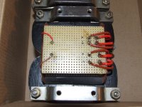
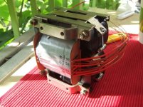
I am sendin pictures of opt/s
They will be measured in amp setup in a little village caled Bac in Serbia, there are some member from this forum living there
Anyway, then I will see if I did my schoolwork good!
Regard, bb
Attachments
Hi!The formulas:
P= I2R
P= V2/R
Both work so long as the current or voltage are in RMS values. They produce huge high side errors if you mistakenly use peak or peak-2-peak values instead.
What kind of V (voltage)? The supply DC (B+) or the amplified signal's AC voltage?
Greets:
Tyimo
- Status
- This old topic is closed. If you want to reopen this topic, contact a moderator using the "Report Post" button.
- Home
- Amplifiers
- Tubes / Valves
- Tube output power for OPT calculation