


Current Source
Costiss,
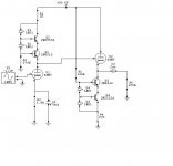
A very simple SS design is the C4S (John Camille) used in all of the bottlehead designs. Gary Pimm also has it on his site but, do not remember if included the formulas). Here is a schematic of a 6SN7 Foreplay w/different bias points. Note: use a MJE340/MJE350 in place of the 6519/6516 - my version of Circuit Maker does not have a model.
ALBQ
To adjust current:
Voltage Amp
I = .95/R1
R2 = B+/.002 (adj for 2mA)
Cathode Follower
I = .95/R4
R5 = B+/.002 (adj for 2mA)
http://mywebpages.comcast.net/gillespie147/AlbuquerqueAudio-MainPage.html
Costiss,
A very simple SS design is the C4S (John Camille) used in all of the bottlehead designs. Gary Pimm also has it on his site but, do not remember if included the formulas). Here is a schematic of a 6SN7 Foreplay w/different bias points. Note: use a MJE340/MJE350 in place of the 6519/6516 - my version of Circuit Maker does not have a model.
ALBQ
To adjust current:
Voltage Amp
I = .95/R1
R2 = B+/.002 (adj for 2mA)
Cathode Follower
I = .95/R4
R5 = B+/.002 (adj for 2mA)
http://mywebpages.comcast.net/gillespie147/AlbuquerqueAudio-MainPage.html
Attachments
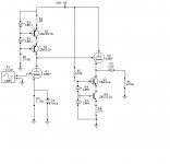
The ccs is drawn wrongly particularly the current source where the transistors are position in the wrong legs. Also anode of the first diode D1 should go to B+ not after. sink legs are fine but the biasing look odd. The cathode of the last led D3 in the cathode follower is place wrongly it should go to ground not the emitter of Q4
Yeah, thought something looked a bit WRONG about that...
An externally hosted image should be here but it was not working when we last tested it.
To adjust current
Voltage Amp
I = .95/R1
R2 = B+/.002 (adj for 2mA)
Cathode Follower
I = .95/R4
R5 = B+/.002 (adj for 2mA):
For the voltage amp the formula looks fine as the pnp drop is around 0.4-0.6max.
But for the cathode follower utilizing npn i think it should be 1.2/r4 atleast as the npn voltage drop is 0.6normally -0.7v
2ma for a 6sn7 seems very low right? they a dissapation of 5.5 watts combined or atleast 2watts per plate. Why run them so low? is that their sweet spot?
6SN7 op points
NickC,
I am playing around (trying to voice) a C4S 6SN7 on my test bench. The values on the schematic are really not where I am running it today. I started with a 6SN7 VTV-Foreplay mix based on the VTV 6SN7 and a table posted on Audio Asylum by Paul Joppa March 20, 01 --> ~330V B+ (VTV) and .9mA VA / 2mA CF (Foreplay 6SN7 op points). I really did not like how it sounded and have been playing with the circuit off and on for a month or so. Current circuit is 180V B+ with 500ohm VA for 2mA design/2.4ma measured and 270ohm CF for 3.5mA design/4.4mA measured. The main reason for the as designed/measured difference is I am not always changing the LED current set resistors each time I do a tweak because I am to lazy to replace all of the resistors for every tweak - remember is 4x boards/tweak. Once I get the circuit "voiced" how I like it, I will lock everything down with the correct values/settings/etc... Also, I agree with you, 1mA for a 6SN7 does not sound good IMO. That said, I am trying to get a mix between the VTV (dark, rich, depth, dead quiet but, lacks excitement - IMO) and the Foreplay (light, detailed, soundstage but, not much bass and sometimes, too light - IMO). I like aspects of both and am cross building the two designs. The C4S's adds life/sparkle/excitement while retaining the inky black background and dark/rich goodness of the VTV. When I get it right (+pun - see my previous schematic oops), will publish the schematic and pictures if anyone is interested.
ALBQ
6SN7 Operating Points
NickC,
Sorry forgot - what I am finding is that as I back off on the current, 6SN7s (IMO) sound more airy/detailed while losing some of their smoothness. As I really like the sound of my Foreplay - detail/openess, and like it better since replacing the 12AU7s with 12BH7s - smoothness/depth, I am trying to blend the best of both the designs. Foreplay 12AU7 detail/open/excitement and VTV richness/smoothness/quiet
ALBQ
PS - ideas are welcome - might be a cool thread - update of the VTV design and/or 6SN7 C4S Foreplay
- Status
- This old topic is closed. If you want to reopen this topic, contact a moderator using the "Report Post" button.
- Home
- Amplifiers
- Tubes / Valves
- current source...