Hello all-
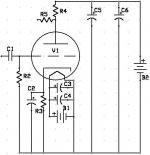
Today I set to work with 6 D cell batteries and 16 AA batteries... Since it is Christmas Eve and RadioShack, etc. are closed, I have no battery holders, so everything is taped together. heh The amp is breadboarded (yes... on a plug board... no solder anywhere...). I used 4 D's in series for the heater (6V@~600mA continuous) and 16 AA in series for 24V@25mA for the plate. Much to my surprise after working on this for a while, it worked!!! And it soudns pretty darn good. Values for schematic are:
B1- 6V (4x D cell)
B2- 24V (16x AA)
C1- 2.2uF (cheap film)
C2- 470uF, 16V Rubycon
C3, C4- 36,000uF Sprague Powerlytic
C5- 470uF, 25V Rubycon
C6- 1000uF, 25V Rubycon
R2- 100k
R3- 1k
R4- 10k
R5- 100k
V1- 6GM8
The output with and without the cathode bypass cap was WAY too high, so I added the 100k resistor on the output. This is essentially a preamp... and it will be running to my headphone amp. So, the amp already can stand alone without a preamp, but I want the tube there for the more tubey sound (my amp is just a buffered amp with OPA2132 and BUF634 right now).
I removed the cathode bypass cap, but I do believe the amp sounded better with the cap in place. What else could I do to reduce the overall output? With the gain from the tube (about 14) before my amp's gain of 11, it is rather loud. I tried a resistor on the input, but it got muffled sounding. Does anyone have suggestions?
The schematic is attached... thanks to anyone who can provide some tips.
Attachments
Have you tried an input level control?
Congratulations on getting it to work. You may want to try a 100K logarithmic potentiometer between the input and the bottom (B-) rail, with the wiper connected to C1 input and the two ends connected across the output of your device feeding this circuit. It will work just like a regular volume control. Your problem now is that you are getting the full output of the circuit, so you need some sort of level control on the input.
Congratulations on getting it to work. You may want to try a 100K logarithmic potentiometer between the input and the bottom (B-) rail, with the wiper connected to C1 input and the two ends connected across the output of your device feeding this circuit. It will work just like a regular volume control. Your problem now is that you are getting the full output of the circuit, so you need some sort of level control on the input.
- Status
- This old topic is closed. If you want to reopen this topic, contact a moderator using the "Report Post" button.