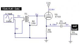
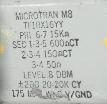
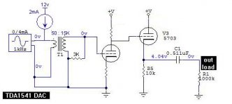
Yet another CD player mod, this one a Magnavox CDB560 that has a TDA1541 DAC chip. In place of the op-amps, I used a pair of Microtran M8 transformers that claim 20Hz-20KHz within 2dB frequency response. The DAC chip feeds into the 150 ohm winding, and the cathode follower grid sees the 15K winding, which is loaded with a 15K resistor. The transformers should attenuate supersonic clock noise. I used some Western Electric caps, 0.511uF as I had them laying around, though I think the magic happens in the tubes. 
The tubes are subminis, low mu triodes, 5703s.
The tubes are subminis, low mu triodes, 5703s.
Attachments
It's now slicker now that I added the 0.1uF film bypass caps in parallel to the existing 0.22uF SMT ceramic caps to the TDA1541 DAC chip,
 as mentioned at Lampizator's TDA1541 page. I hear some soundstage

Last edited:
Hi,
I've always been interested in this approach.
So the D/A's I/V resistor equivalent is 15k/100 =150 ohm?
Would like to ask if you nulled the DC offset, or if you have that running through the secondary winding (as it is) with the M8 running essentially back to front.
Regards,
Shane
I've always been interested in this approach.
So the D/A's I/V resistor equivalent is 15k/100 =150 ohm?
Would like to ask if you nulled the DC offset, or if you have that running through the secondary winding (as it is) with the M8 running essentially back to front.
Regards,
Shane
So the D/A's I/V resistor equivalent is 15k/100 =150 ohm?
Would like to ask if you nulled the DC offset, or if you have that running through the secondary winding (as it is) with the M8 running essentially back to front.
I didn't do anything about the DC offset, so it's running thru the transformer.
could your circuit be adapted for balanced 1541 config? 2 x1541 with +/- signal
It should work. At least with the transformers I used, they have centertaps, you could have one TDA1541 feed one end, the inverted TDA1541 feed the other end, and the centertap going to ground.
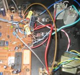
Took care of some other problems, mostly the display that shows track number was bad. Got a Philips player that was nearly identical, CD460/07R and swapped out the control board that also has the display (a module from the Philippines) that is some strange custom job Philips must have ordered. While I was in there, I swapped out the transport door for fun, it has blue trim instead of red. And changed the LED that lights up the spinning CD from green to a white one gotten off a Xmas light string. And I had to add an LED for the remote indication, so I used a blue LED. To reduce the brightness I put in parallel with that LED a 470 ohm resistor to divert current. So it looks somewhat customized externally, while it has the tube analog audio circuits inside.
And changed the LED that lights up the spinning CD from green to a white one gotten off a Xmas light string. And I had to add an LED for the remote indication, so I used a blue LED. To reduce the brightness I put in parallel with that LED a 470 ohm resistor to divert current. So it looks somewhat customized externally, while it has the tube analog audio circuits inside.Attachments
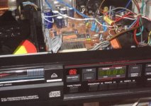
Took care of some other problems, mostly the display that shows track number was bad. Got a Philips player that was nearly identical, CD460/07R and swapped out the control board that also has the display (a module from the Philippines) that is some strange custom job Philips must have ordered. While I was in there, I swapped out the transport door for fun, it has blue trim instead of red.
Took care of some other problems, mostly the display that shows track number was bad. Got a Philips player that was nearly identical, CD460/07R and swapped out the control board that also has the display (a module from the Philippines) that is some strange custom job Philips must have ordered. While I was in there, I swapped out the transport door for fun, it has blue trim instead of red.
The old Philips CD players are known for their display problems (I guess the same applies to your player). These issues can be resolved using Micrel MM5450 chip.
Yet another CD player mod, this one a Magnavox CDB560 that has a TDA1541 DAC chip. In place of the op-amps, I used a pair of Microtran M8 transformers that claim 20Hz-20KHz within 2dB frequency response. The DAC chip feeds into the 150 ohm winding, and the cathode follower grid sees the 15K winding, which is loaded with a 15K resistor. The transformers should attenuate supersonic clock noise. I used some Western Electric caps, 0.511uF as I had them laying around, though I think the magic happens in the tubes.
The tubes are subminis, low mu triodes, 5703s.
Schema looks great
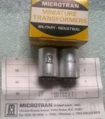
I have plan for my Microtran M8:
1. As preampli step- down transformer. Is it safe if they are working in high voltage ?
2. As step-up tranny like what you're using. I'll take DAC chip AKM4396. It has some DC offset, so I need a interstage Capacitor. Are this M8 convenient with AKM4396?
Regards,
Schema looks great
I have plan for my Microtran M8:
1. As preampli step- down transformer. Is it safe if they are working in high voltage ?
2. As step-up tranny like what you're using. I'll take DAC chip AKM4396. It has some DC offset, so I need a interstage Capacitor. Are this M8 convenient with AKM4396?
Regards,
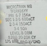
According to the specs listed on the M8 transformer, it should be able to handle 175VDC from its primary to its secondary. These were designed with tubes in mind.
If you use the positive analog audio output, and the negative analog audio output pair (of either the left or right channel of your DAC chip), you should be able to avoid any significant DC offset. The AKM4396 spec sheet says it can handle 1K loads, so you may need series resistors like 1K, between the outputs and the transformer 600 ohm winding. We want to avoid causing distortion from exceeding the output's current ability, which looks to be +-3mA, the current you get with their specified 1K load resistor. I don't think you'd need to connect the 600 ohm winding centertap to anything (any DC offsets should cancel).
Tks for your reply.
My microtran is M8-A and very small. I cannot see Working voltage mark on it as like yours (175V WV). So I'm not sure as if they can use in high voltage (plan of pre tube 26 running 150V in parafeed circuit).
Attachments
I suspect that your transformers are the same as mine, except for the package. See if you have a spec saying "level 8dBm". If so, it's quite likely you can apply the 150VDC.
M8-X has some variations based on package. I hope my M8-A can run 150V
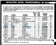
http://www.technicalaudio.com/pdf/MicroTran/Microtran_miniature_transformers_catalog_1974.pdf
Attachments
Interested to join the discussion.
Would appreciate some comments of the improvement (or so i think it is) from the original circuit by OP. Basically, i'm addressing the issue of voltage offset on the TDA1541 (The spec sheet expects as little offset as possible on its output, stating +- 25mV as maximum). Hence, i am suggesting these changes:
1. 2mA CCS load on the TDA1541 output
There is a -2mA standing current on the output pin when no signal is presented. I don't know what is the winding resistance of the transformer, but even if it's, say, 10R then there will be an offset of 10R*-2mA = -20mV on the output. This may seem small but we can reduce this to 0v by adding the 2mA CCS.
2. Use the 50R tap as primary to the TDA1541 output and load the 15k secondary with 3K resistor.
This would mirror a load of only 10R on the primary. Against the 4mA peak-to-peak current swing of the TDA1541 when there is a signal, this would translate to a voltage swing of only +-20mV-peak (40mV-pp) on the TDA's output which is within the limit of the spec sheet. This is definitely smaller than the current load of 150R as shown on OP's circuit which is translating to an offset of +-300mV-peak (much too high to maintain low THD). There is a drawback to this approach which is the necessity of having a gain stage. The 20mV-peak on the primary would translate to about 340mV-peak on the secondary winding. This is lower than the typical line level of 2Vrms. Fortunately, a 12AX7 gain stage has more than enough gain to bring it up with spare for some negative feedback (and even lower THD). The schematic i attach doesn't show this negative feedback but there is plenty of info on this forum about this.
So, am i making any sense? Is there something i'm missing?
Attachments
Last edited:
- Status
- This old topic is closed. If you want to reopen this topic, contact a moderator using the "Report Post" button.
- Home
- Amplifiers
- Tubes / Valves
- Another CD player tube mod, TDA1541 with transformers and triode cathode followers