Hi
I have post this on analog board, I want to move it to here but no can do.
Sorry to post it again......
I recently built a LCR phono stage, but it has a 120Hz hum unsolved.
I wrote blogs about it: (sorry, in Taiwanese, please use google translation...)
Coffin BLOG: LCR PHONO Pt.1
Coffin BLOG: LCR PHONO Pt.2
please give me some advice about the hum.
cheers
Coffin
Please post schematics and pictures here. Asking the membership to deal with terrible translations of your blog is not only unfair, but unlikely to get you the help you seek. 
 You should have asked a moderator for help to move your thread. I will now go and delete it. Please read the rules.
You should have asked a moderator for help to move your thread. I will now go and delete it. Please read the rules.Hi
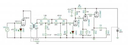
MY diy LCR phono was built with:
first stage - EC8010, LED bias, 15K:600 interstage
RIAA EQ - 600 Ohm LCR
second stage - E88CC, LED bias , direct-coupled to
third stage - 5687 common cathode, direct-coupled to
fourth stage - 5687 follower, capacitor-coupled
HV is Salas SHHV2, all heaters are DC and twisted.
Inductor modules are wrapped with 0.1mm permalloy grounded.
Ground on preamp board is not star-grounded, just a sequential grounded bus, 2mm solid wire.
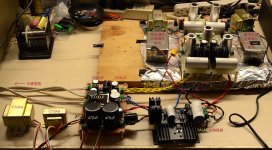
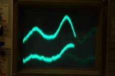
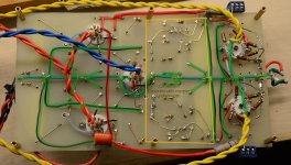
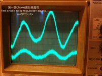
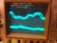
I attach the schematics, testing scene, and hum wave form(10mV/2ms div, up is left channel and down is right channel).
please advice, thanks a lotttt
Coffin
MY diy LCR phono was built with:
first stage - EC8010, LED bias, 15K:600 interstage
RIAA EQ - 600 Ohm LCR
second stage - E88CC, LED bias , direct-coupled to
third stage - 5687 common cathode, direct-coupled to
fourth stage - 5687 follower, capacitor-coupled
HV is Salas SHHV2, all heaters are DC and twisted.
Inductor modules are wrapped with 0.1mm permalloy grounded.
Ground on preamp board is not star-grounded, just a sequential grounded bus, 2mm solid wire.
I attach the schematics, testing scene, and hum wave form(10mV/2ms div, up is left channel and down is right channel).
please advice, thanks a lotttt
Coffin
Attachments
Are your filaments AC or DC and can you provide some information on the supply transformer and its location?
The most likely source for a problem like this usually is either magnetic induction into the 15K:600 transformer or the LCR equalizer module.
Some pictures of your construction technique may help. (Under board) I use ground bus myself with no hum issues in any of my designs - grounded at only one point?
You need to put the whole thing in a metal box, the aluminum foil helps with electrostatic coupling provided it is connected to your circuit ground. (I do this too, but expect some noise..) The audio transformers need to have their endbells/core properly grounded. It looks to me like the foil does not extend under the EC8010 which you need to do.
Kevin,
Transformers:
Now I use 2 transformers: EI for B+ and Toroid for LT. Originally I placed them at about 25cm from preamp, but not only the circuit hummed but also showed some spikes on the scope. Now I place them away from preamp at about 1 meter, then the spikes are gone.
Filament:
I use 3 secondaries for EC8010/E88CC/5687.
EC8010's uses LM1085 regulating at 6.3V for both channel.
E88CC's uses LM1085 for current regulating at 300mA, adjustable.
5687's uses LM317 for current regulating at 450mA, adjustable, for both channel.
B+:
Full wave bridge rectifiers -->LCLC --> Salas SHHV2, F+/F0 twisted, S+/S0 twisted.
Preamp:
Inductor modules are connected to ground via 10R//0.01uF, also the interstage and aluminum foil(which did extend under the EC8010s). Underneath the RC section I paste a grounded copper foil insulated from solder joints. Input 47K resistors are paralleled with 50pF. All grid stoppers are directly soldered to pins of the sockets.
I have tried to swap the tube. Strangely when I used an old Philips Heerlen E88CC, the hum was largely reduced! But the plate current was too small to get the right operation point.....
I'll manage to take a picture of the board underneath.
cheers
Coffin
Hi Coffin,
try a step by step approach to isolate the cause of the hum. This essay may help for the initial steps:
VinylSavor: Trouble Shooting Hum
Best regards
Thomas
try a step by step approach to isolate the cause of the hum. This essay may help for the initial steps:
VinylSavor: Trouble Shooting Hum
Best regards
Thomas
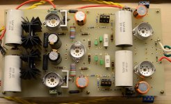
Some pictures of your construction technique may help. (Under board) I use ground bus myself with no hum issues in any of my designs - grounded at only one point?
Kevin,
Here the above and bottom of the amp board.
Thanks!!
Coffin
Attachments
You may need to put the preamp within a fully shielded enclosure.
Frank,
Thanks for the tip. I don't have suitable chassis on hand right now.
cheers
Coffin
Hi!
Why don't you try to isolate the area where hum is introduced as suggested in the article I linked? Once you know where hum is injected it will be much easier to proceed from there.
Best regards
Thomas
Thomas,
Yes I'm trying now.... The most possible place is the first stage with interstage/LCR. Still doing some shielding but ineffective.
cheers
Coffin
First thing you need to do is short to ground the first gainstage inputs close to the tube socket. Then look at the hum. But really, the audio portion of the circuit must fully shielded. And it is often better to have a separate ground line for the power supply and star ground at the power supply board. Sometimes floating the filament is better.
Last edited:
The process goes slowly....
I had changed the operating points of those tubes, because I think originally I'm too optimistic to set the current at 40mA up for one channel. This would lead the tranny giving a huge amount of EMF which was really bad for phono stage, let alone I used a choke input regulation also carrying EMF. Now I set the current at 45mA for 2 channels, and this make the hum goes down a little bit. Now I'm waiting the new transformer which voltage is adequate to build a C input regulation.
cheers
Coffin
- Status
- This old topic is closed. If you want to reopen this topic, contact a moderator using the "Report Post" button.
- Home
- Amplifiers
- Tubes / Valves
- My LCR phono with HUM....