Does the phase relationship matter when wiring a transformer with dual primaries? I have this small transformer I was going to use for a preamp. I'm wiring it with 3,2 and 4,1 tied together because that's the way it looked on the PCB. I wired up a capacitor (CRCRC) filter to it with a regulated filament supply that has a B+ reference at roughly 1/4 B+. If I ramp it up on my variac, the transformer starts to growl. If I eliminate everything but the first cap section of the B+ supply and it seems fine. Can the cap size actually overload the power transformer?
Is it a phase issue with the primaries?
Thanks,
Blair
Is it a phase issue with the primaries?
An externally hosted image should be here but it was not working when we last tested it.
Thanks,
Blair
Yes, the phase matters.
Use a Mains Bulb Tester to check your wiring at every stage of your assembly.
Don't use the Variac until after you know the wiring is correct.
A major fault causing excess transformer current could burn out the transformer and with luck also burn out your Variac.
Use a Mains Bulb Tester to check your wiring at every stage of your assembly.
Don't use the Variac until after you know the wiring is correct.
A major fault causing excess transformer current could burn out the transformer and with luck also burn out your Variac.
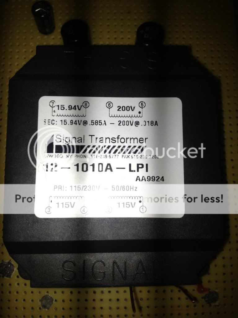
The dual primary, wired in series, is for 230V input.
If you only put in 115 then you will only get 1/2 of the 15.94V and only half of the 200V.
If you are using a 115V supply then 2,4 should be connected together and 1,3 should be connected together.
Be safe.
You did not mention a diode bridge...perhaps a schematic of what you are doing would help us help you.
")
If you only put in 115 then you will only get 1/2 of the 15.94V and only half of the 200V.
If you are using a 115V supply then 2,4 should be connected together and 1,3 should be connected together.
Be safe.
You did not mention a diode bridge...perhaps a schematic of what you are doing would help us help you.
The dual primary, wired in series, is for 230V input.
If you only put in 115 then you will only get 1/2 of the 15.94V and only half of the 200V.
If you are using a 115V supply then 2,4 should be connected together and 1,3 should be connected together.
Be safe.
You did not mention a diode bridge...perhaps a schematic of what you are doing would help us help you.
DUG,
You seem to know what you are talking about and I am just curious about the other combinations to this unusual transformer. I hope that this is not too much to bother you with, but I can't find an answer on the internet (probably using the wrong terminology for the transformer and search) and I want to learn without blowing myself up one day.
What if 1 & 2 were only connected (and 3 & 4 not connected to mains)? You would still get the half of the voltage output, but would the current be halved?
And without connecting 1 & 3 and 2 & 4, but each plugged in to mains separately as 1 & 2 and 3 & 4, would it still yield the same output with respect to voltage and current as 1 & 3 and 2 & 4? Or would something bad happen?
Thanks.
Connect 1&2 to 115Vac mains and you get the correct output voltage. But your input is strangled. You end up with ~ half the current.
Same if you connect just 3&4 to 115Vac mains , you get ~ half current.
Dug got this bit right
Use the Bulb Tester for every power up until no more modifications are made.
Same if you connect just 3&4 to 115Vac mains , you get ~ half current.
Dug got this bit right
You need to power up with a Bulb Tester just in case the manufacturer got the wires swapped.If you are using a 115V supply then 2,4 should be connected together and 1,3 should be connected together.
Use the Bulb Tester for every power up until no more modifications are made.
Sorry I did not chime back in. Our home had a hot water heater rupture, and we are in a hotel. Yay!
I swear I traced the transformer primaries out to be the way I described, but the transformer growls like two primaries out of phase. It's an oddball with a C core style and dual windings. I doubt, "Signal" marked the phase wrong.
I will swap them and see. I am familiar with tube power supplies, so there is a FWB and a proper execution.
Thanks!
Blair
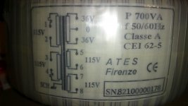
Wake up old thread!!
I have two toroidals that have the similar issue that decide67 mentioned. Most of the phase marking are on 1 and 3 or 2 and 4 but decide67 is back to back on the primaries and therefore your would 1 and 3 and 2 and 4. Have a look at the picture on my toroidal. Does the zigzag line represent the phase?
I have two toroidals that have the similar issue that decide67 mentioned. Most of the phase marking are on 1 and 3 or 2 and 4 but decide67 is back to back on the primaries and therefore your would 1 and 3 and 2 and 4. Have a look at the picture on my toroidal. Does the zigzag line represent the phase?
Attachments
...
Does the zigzag line represent the phase?
Probably, but as AndrewT says:
Yes, the phase matters.
Use a Mains Bulb Tester to check your wiring at every stage of your assembly.
Don't use the Variac until after you know the wiring is correct.
...
Not too sure
Thanks, but I'm not sure how a bulb on series would tell me the phaseing. I could check for continuity of each coil. Or do I power up one primary coil and then check for current between the hot on the powered coil and the leads for the other primary. Would the other primary NE charged but the magnetic field created by the charged coil? So the hot from the live coil would have current flow to the common on the imcharged coil?
Thanks, but I'm not sure how a bulb on series would tell me the phaseing. I could check for continuity of each coil. Or do I power up one primary coil and then check for current between the hot on the powered coil and the leads for the other primary. Would the other primary NE charged but the magnetic field created by the charged coil? So the hot from the live coil would have current flow to the common on the imcharged coil?
Just connect one of the primaries to power i.e. 1 and 2, then measure the voltage between 1 and 3 and 1 and 4, you will have almost no potential between the "top" of each winding and full potential between a "top" and a "bottom". So if you measure a few volts between 1 and 3 and 115V between 1 and 4, then for 115V operation 1 and 3 are connected together and 2 and 4 are connected together, or for 230V operation AC is applied on 1 and 4 and 2 and 3 are tied together. This test will work even if your in a 230V part of the world, just apply 230V to one primary and do the same measurements, obviously your voltages will be a few volts and 230V potential, pretty straight forward.
Best of luck
Peter
Best of luck
Peter
If those little wiggles do indicate thermal fuses, then be careful. Overheating either one will make your transformer scrap.
They generally don't reset when the transformer cools down.
DF left out another advantage/protection from his list.
They generally don't reset when the transformer cools down.
DF left out another advantage/protection from his list.
The Mains Bulb Tester also protects the mains fuse!protects you, your house wiring and the transformer if you get it wrong.
- Status
- This old topic is closed. If you want to reopen this topic, contact a moderator using the "Report Post" button.
- Home
- Amplifiers
- Tubes / Valves
- Transformers with dual primaries?