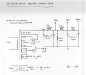
I'm new here and I hope I have posted this in the right place. I have built 300B amps from the JE labs schematics - the deluxe version.(easy to find on the web) It all works but my B+ is to high by about 25v --the power from my transformer is to high. So all my voltages are slightly high. Someone told me to put resisters before the first choke, but they were not sure. Where is the best place to add resisters to drop it the voltage?. My 5v and 6.3 v are fine-- I have plenty of 50w resisters to play with. I am using Shuguang 300BS-B and they are rated at 480 max plate voltage. Any advice is greatly appreciated. the schematic is here. I am not quite sure how to put it in the post so I have just added a web page link http://jelabsarch.blogspot.com/2012/06/je-labs-se300b-classic-and-deluxe.html
Last edited:
I don't know the circuitry. If a 5AR4 vacuum rectifier is being used to rectify the B+, switching to a 5R4 will lower the rail voltage by quite a bit. The 5R4 can't work into as large a 1st cap. as the 5AR4 can. Play safe and use 15 μF. as the value for the 1st position. Use a CL90 inrush current limiting thermistor to slow B+ rise.
BTW, the forward drop in a 5R4 is greater than that in a 5U4 too.
BTW, the forward drop in a 5R4 is greater than that in a 5U4 too.
Provided that neither the rated plate voltage or dissipation of the 300B are exceeded you may not need to do anything.
A schematic of the amplifier or at least information on the type of rectification, and whether the output stage uses cathode bias or fixed bias along with plate voltage and current would be helpful in answering this question.
A schematic of the amplifier or at least information on the type of rectification, and whether the output stage uses cathode bias or fixed bias along with plate voltage and current would be helpful in answering this question.
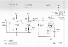
On 300B You have 355 v, that is OK.
But problem. IMO, is that there are direct coupled triodes in preampl.
You can adjust modes of first and second triodes, that cathode of second triode will have for a 8 v more than plate of first triode. Try use 62 or 72 kohm instead 68 kohm, and 22 or 27 kohm instead 24 kohm to receive 8 v difference.
First plate must be lower to 8 v than cathode of second triode.
Regards!
Hi,
do what azazello sayd. Some Volts more or less doesnt mean anything to a tubeamp.
Have fun,
Hilmar
Edit:
Another Thing you can do is: Swap the first cap in your powersup to the second cap (47µ +47µ) and play at the position of the first cap with small capacitances maybe less than 1µ. You will get less tension the smaller the first cap is. Try to simulate this before with PSUD from Duncan-Amps.
Last edited:
So instead of 436v I get 456v ect. I had the transformers wound years ago and obviously they didn't quite get them right.
That's only 4.6% high. Sounds pretty good to me!
I dont know which is your final schem, but based on your first post, you can cut the line of 390 volts ..Place an ammeter in series.( careful with the probe polarity) Power-up and register the current. Devide your excess voltage (25v) with the registered current and you can find the value of resistor in ohms..add this resistor value with your existing 4.7k..Hope this help
Mosfet in PS, I'm afraid, will decrease dynamic of sounding....IMO /I tried in my SE 300B..../

Don't worry about those 20v. I've seen differences like that from same type valves, different brands, even same socket different time of day! This is less than 10% deviation, you're good.
It's still well within your 300b rating. I've built the 2a3dx and have had the B+ as high as 390v B+ (355v on the schema) without realising on shuguang 2a3C with no technical problems.
I've since added a dropping resistor before the choke to be able to try vintage RCA 2a3. I've read it said that the dropping resistor in this position has a negative impact on the sound. I didn't notice this. What it did was lower the noise and hum on the PS on my implementation so its stayed in there although I prefer to listen through the Shuguang 2a3C.
Just enjoy it now and maybe later on try azazello's recommendations. Good luck!
Hi,
Semiconductors having specs , Valves having guidelines....")
Old eqipment are not fitted with regulated mains supplies. The mains voltage had much more variation in the old days than it has today.
Even today where some new build valve gear comes up, the mains is stable enough to keep the specs over a long period for safe operation without the need for regulated mains supplies.
Many good designed HI Fi top gear from the sixties without any sort of power stabilizers are still working today and enjoy their owner.
73
Wolfgang
That's only 4.6% high. Sounds pretty good to me!
Semiconductors having specs , Valves having guidelines....
Old eqipment are not fitted with regulated mains supplies. The mains voltage had much more variation in the old days than it has today.
Even today where some new build valve gear comes up, the mains is stable enough to keep the specs over a long period for safe operation without the need for regulated mains supplies.
Many good designed HI Fi top gear from the sixties without any sort of power stabilizers are still working today and enjoy their owner.
73
Wolfgang
I will look into that, My main concern is my transformer. I want to drop the power after the GZ37 as I am reading about 20v to high. So instead of 436v I get 456v ect. I had the transformers wound years ago and obviously they didn't quite get them right.
Well, I wouldn't dis your transformers. It wouldn't take so much high line v to help nudge it up a bit.
If the over V bugs you, maybe it would be worth it to try a series CCS and an adjustable shunt regulator after the first filter choke? Not so hard to do, they can often make a really positive contribution to the sound. A CCS with a low voltage requirement for compliance and a shunt regulator that is able to take the load current until everything else draws. . .
S.reg. lore is that you want to draw as much current through the regulator as through the load but I've run circuits with a lot less and still managed to get worthwhile results.
I would likewise say, just leave it.
Datasheets mostly show 300Va-f as 300V, but maximum specified voltage for a tube has always been tied to (safe) normal operation. A few other specs for a "new" version specify 450V. It is not as if the tube will spark inside with 10% overvoltage. Many power tubes can by used at 140% spec.ed Va and come to no harm. One often sees some other application for the same tube suddenly being able to handle double the "max" Va (e.g. EL84 being used in some circuits with Va=700V, to mention only one of several examples).
A colleague having made and tested EL34s in the Philips Endhoven factory long ago confirmed this. Perhaps other of the tube veterans here can comment on what exactly is meant by a tube's Va.max, provided max. dissipation and heater voltages are kept in line.
- Status
- This old topic is closed. If you want to reopen this topic, contact a moderator using the "Report Post" button.
- Home
- Amplifiers
- Tubes / Valves
- How can I drop B+ Voltage