Hi Guys,
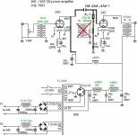
I want to try to change my amp, from interstage transformer coupled to cap coupled, I'll try 0.22 uf copper foil in oil coupling cap.
But I have a doubt,do I have to put a resistor? if so what value should I use?
Please see the attach.
thanks for the help.
I want to try to change my amp, from interstage transformer coupled to cap coupled, I'll try 0.22 uf copper foil in oil coupling cap.
But I have a doubt,do I have to put a resistor? if so what value should I use?
Please see the attach.
thanks for the help.
Attachments
You can use the primary of your IT as a plate choke and capacitor couple to the second 845. Leave the secondary unconnected. Hopefully despite the 5K primary impedance rating the "choke" (IT primary) has sufficient inductance for good bass response.
This may help HF performance if the IT is not best quality, but note that you are also going to loose about 3dB of voltage gain. I am not sure a 5K:10K IT is optimum for a 845 either in terms of loading given its fairly high rp.
Long term a proper audio choke is the best solution. (80 - 100mA, > 60H)
A resistive load is not a good idea unless you want to further reduce gain and compromise output power due to the large voltage drop across it. A large power resistor would be required, and ideally a much higher plate voltage for the driver stage. Another option would be a CCS since the voltages aren't too high, but again more B+ is probably required.
You just can't do that. First you need to load the anode. I would try with the secondary of that interstage as this should have higher inductance. Using a resistor is not possible because your plate voltage is already quite low at 450V. Assuming the inductance of the secondary is around 35H, maybe 40 if it is a good one, then you need a proper grid resistance for the output stage. Given the inductance and the fact that high values are not recommended for tubes like the 845, a value around 10-12K is a good compromise. From this you can see that 0.22 uF for the coupling capacitor is not appropriate as you will have a resonance around 55-60Hz! You need something like 4 uF/1000V to shift it down close to 10 Hz.
A bad idea in my opinion. There is no guarantee that the IT secondary can carry the same plate current as the primary. Most will not, in which case it will open up and ruin the transformer. Then you can never go back and you're stuck with only using it for an expensive choke. Do as Kevin says and use the primary. I would also perhaps consider loading the secondary with a suitable resistor. And yes, you will loose gain so why even do this?You just can't do that. First you need to load the anode. I would try with the secondary of that interstage as this should have higher inductance.
A bad idea in my opinion. There is no guarantee that the IT secondary can carry the same plate current as the primary. Most will not, in which case it will open up and ruin the transformer. Then you can never go back and you're stuck with only using it for an expensive choke. Do as Kevin says and use the primary. I would also perhaps consider loading the secondary with a suitable resistor.
Instead I don't think it is a bad idea. That transformer is for a primary current up to 80 mA whereas the current used in the actual driver is only 45 mA. So, considering the ratio, if you run 45 mA into the secondary the DC induction will be about the same (actually will be less!) as the primary run at 80 mA and leaving enough margin for the signal.
Last edited:
So, are willing to buy him a new one if it fails? I'll bet not!Instead I don't think it is a bad idea.
So, are willing to buy him a new one if it fails? I'll bet not!
I don't need to buy a new one. If you knew how a transformer works and read the schematics you could figure it out by yourself....
The DC induction is directly proportional to both the number of turns and DC current. As this one has N1 primary turns and about N2 = 1.4xN1 secondary turns you can run a DC current into the secondary that is about 70% of that you can run into the primary (i.e. 56 mA, in this case).
<snip>
The DC induction is directly proportional to both the number of turns and DC current. As this one has N1 primary turns and about N2 = 1.4xN1 secondary turns you can run a DC current into the secondary that is about 70% of that you can run into the primary (i.e. 56 mA, in this case).
This is assuming the wire gauge is sufficient to support the current without excessive heating, I don't know that for sure so I didn't recommend it. You can also wire the primary and secondary in series (aiding) to get more than 4x the primary inductance alone, but again you need to know something about the limits of the copper and core to do this safely. I figure no more than ~35mA for this configuration. A proper choke would be soooo much better and a safer bet.
I want to try to change my amp, from interstage transformer coupled to cap coupled, I'll try 0.22 uf copper foil in oil coupling cap.
You can use one capacitor of small value, eg. 1000 pico Farrad which connects from plate of first tube to gird 's power tube while IT stay there. This improve the high frequencies.
This is assuming the wire gauge is sufficient to support the current without excessive heating, I don't know that for sure so I didn't recommend it.
Will be fine if using it as a choke. A current density up to 2A per square mm is normal for chokes and supply transformers whereas 0.8-1A per square mm is more typical in (good) signal transformers. Up to 3A per square mm will not happen anything strange.
Before spending additional money one can do such experiment as in my opinion the big problem of that amplifier is certainly NOT the interstage....

Here are the Tamura STU 5K specs:
http://www.tubebooks.org/file_downloads/tango_tamura/Tamura_STU-5K.pdf
The primary has 750R resistance in the best case and the secondary has 1600R in the worst case. As the ratio is 1:1.4 then the secondary would have about 1150R resistance for the same number of turns.
Now assuming that an AWG 32 wire (i.e. 0.2 mm) has been used for the primary (which is quite small and would imply a current density around 2.5A/mm^2 and 4.8W heat for 80 mA) the secondary cannot be too small to keep such resistance ratio and actually the AWG 34 will do perfectly! AWG 34 means 0.16 mm diameter. Then if 45 mA are used the current density will be 2.24 A/mm^2 and 3.24W heat. So it is better!
To get it to work in the same condition as the primary with 80 mA DC in terms of heat one needs to go up to 55mA (with about 2.7 A/mm^2 which is still quite safe) while in terms of current density one needs to go up 51 mA in the secondary (and the heat will be less).
You can use one capacitor of small value, eg. 1000 pico Farrad which connects from plate of first tube to gird 's power tube while IT stay there. This improve the high frequencies.
This only works when the transformer has a ratio of 1:1, this is 1:1.4..
<snip>
Before spending additional money one can do such experiment as in my opinion the big problem of that amplifier is certainly NOT the interstage....
I agree..
That's the Sakuma schematic. How do you like the sound and why do you want to change it?
I don't know enough to judge from the schematic how it might sound but it has always appealed to me in a macho sort of way to have an 845 driving an 845 for, what I guess would be, about 5 watts of output power.
Efficient it is not, manley it is.
I don't know enough to judge from the schematic how it might sound but it has always appealed to me in a macho sort of way to have an 845 driving an 845 for, what I guess would be, about 5 watts of output power.
Efficient it is not, manley it is.
Yes thats a Sakuma - Design.
Sakuma San has a very special philosofie in designing his amps. So the sound is even special too - not really hifi but there must be something in it. Not only in Japan he has a lot of followers.
For me ilike the very individual aproach and its more a piece of art then a technical product.
Driving the endstage with the same tube is like a lens for the character of that tube.
I have made the experience that drivin 300B with 300B cures the "Lowther-shout". In 1million years i will not understand why. But it does.
So if you want to go more in Hifi direction maybe its better to look for another schematic. I think Andrea Ciuffoli from Italy has avery nice 845 Amp driven from a EL34 via Interstage.
Have Fun,
Hilmar
- Status
- This old topic is closed. If you want to reopen this topic, contact a moderator using the "Report Post" button.
- Home
- Amplifiers
- Tubes / Valves
- 845 IT couple amp