I'm a first time builder,had been testing my SE prototype with KT88 and its work fine,when I build the final amp,the biasing goes way to high,my prototype is set at -20V,the actual is 19V,which is fine,but on my final amp,the voltage keep shooting up till the resistor burned,I measure the voltage and it goes up to 50V and seems that it want to climb further more,what have I done wrong?
how to upload the schematic?
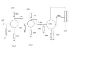
Like this,
To add a photo, files or non standard files.
First click "go advanced" in the box below the "quick reply" message box. Doesn't matter if you decide half way through a message to do that, it carries it forward.
Then click "Manage attachements". Maximise the new Window so that you can see all the text.
Click browse in the first box at the top and find your picture. Repeat for any more pictures.
Click upload... a message appears "uploading"
When complete the files will show as being attached. Now click the small text that says "close this window"
The pictures should now be attached and when you submit your post they will appear.
Make sure your pics aren't too big, a couple of 100k is plenty, and many members object when they are massive and it alters the margins
It tells you in the attachments window what max sizes are allowed.
If you want to attach a file that has a non standard format for example excel, circuit simulation etc then try putting the files in a zipped folder and attaching that.
")
I'm no expert in valve circuitry beyond the basics but if you have a prototype that is OK and the final build is not then three things come to mind, firstly, a basic error in transferring the design over, secondly, are you using the same KT88 as in the prototype ? and thirdly, is the design somehow oscillating. Transformer connections OK ? Have you scoped it ?
Try running it with the 3.3uf grid coupler removed and also the 2.2uf bypass. See if its DC stable in that condition. I assume you have the output tranny terminated into a load at all times.
Try running it with the 3.3uf grid coupler removed and also the 2.2uf bypass. See if its DC stable in that condition. I assume you have the output tranny terminated into a load at all times.
Ok problem solve,Thank You ,it was cause by the faulty 3.3uF capacitor
Thanks for the update.
- Status
- This old topic is closed. If you want to reopen this topic, contact a moderator using the "Report Post" button.
- Home
- Amplifiers
- Tubes / Valves
- Biasing problem