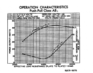
I want to design a monoblock ultralinear (40% taps) power stage with 2 pairs of 6L6GC tubes. The image below is taken from the RCA datasheet. It appears that the best plate-plate resistance for power vs distortion is around 6-8K for a single pair of 6L6's in non-UL mode. I have a couple of questions.
1. How does UL operation change this graph? Does it shift both curves down (less power, less distortion), but keep them looking basically the same in relation to plate-plate resistance? Or are the curves changed significantly.
2. If I use parallel tubes, should I cut the plate-plate resistance in half when I choose an output transformer, since the effective gm of the pair is doubled and the effective ra is halved. It seems many people don't do this.
3. If I am going to run the amplifier barely into AB1, how does this affect the choice of transformer. Do I want a less steep load line (higher plate-plate resistance.)
Hammond actually makes an output transformer (1650T) designed for parallel push-pull operation with 6L6GC tube, and it only has a 1.9K impedance, which I don't understand. Hammond Mfg. - "Classic" Push-Pull - Tube Output Transformers - (1608 - 1620, 1645 & 1650 Series)
I know this is a lot to answer, but there seems to be a real paucity of info on parallel push-pull operation. If somebody could direct me to a reference I'd greatly appreciate it.
Thanks,
mike
Attachments
Current hogging can be a problem, when PPP is employed. It is a given that all the tubes in a channel's set will be closely matched. Good matching is a starting point. "Fixed" bias, with an individual trim pot. for each tube, is in order.
The issue of stress on the driving circuitry DF96 mentioned is exacerbated by the comparatively low grid to ground resistance allowed, when "fixed" bias is employed. I strongly suggest either Mullard or Williamson style small signal circuitry, with source follower buffers DC coupled to the tubed stuff, be employed.
The issue of stress on the driving circuitry DF96 mentioned is exacerbated by the comparatively low grid to ground resistance allowed, when "fixed" bias is employed. I strongly suggest either Mullard or Williamson style small signal circuitry, with source follower buffers DC coupled to the tubed stuff, be employed.
Current hogging can be a problem, when PPP is employed.
How important is this in the real world? I've reviewed every PPP schematic I can find, and most don't use separate bias adjustment per tube. Some use a 20-50ish ohm resistor at the cathodes or/and anodes. Most don't even bother w/ that.
I built basically Pete Milletts parallel pp 807 amp, but regulated all the supplies and bias, and am using even harder to match 829b's for the outputs. So far, no issues. But I am nervous about it. (I spent 2 years building the thing, I'd hate to start developing issues).
Pete took no extra measures to deal w/ the parallel tubes. I guess it wouldn't be too difficult to add another couple caps and pots for the bias adjustment, if needed, though..
Anyway.. some of the threads I've read about parallel tubes make it seem like a bad idea that will never work, and others make it seem like a non issue.
I'm with Eli on this one unless you plan to use only very well matched tubes or some sort of auto biasing scheme. To claim it can't work is foolish considering all of the prosperous and revered manufactures that build PPP amplifiers. Audio Research, Conrad Johnson, McIntosh, Quicksilver and dozens more. There are trade offs in both designs that must be addressed. Some feel that multiple coupling capacitors, even well matched, smear the sound. (ala Jadis...but they screwed it up) However it really all comes down to keeping the output stage as well balanced as possible by whatever means within your design philosophy.How important is this in the real world?
Putting in 4 trimpots for the monoblock doesn't sound that bad. A few more traces on a PCB.
Back to my original question (one of them at least); what should I use for the impedance of the transformer. Should I find a good tradeoff between distortion and power for push-pull, then divide that number by 2 for PPP? Is it that simple? Or should I just find a design from a great company like AR, Conrad Johnson, et al, and use the anode-anode impedance that they use?
I'd really like to give this a try.
Mike
Built a lot of 4 x 6550 amps always used a cap for each tube and bias pot, even made a 12 x 807. Have repaired multiple commercial 4-8 x EL34's that did not use seperate caps and all the tubes had blown up only needs one tube to go and it takes out the rest. Changed the commercial amps to separate caps and no more trouble. Have tried direct coupling with 6Bl7's gets very complicated with 4 tubes, Best to stick to two tubes. never tried it with Mosfets.
You get very good damping with multiple tubes.
Phil
You get very good damping with multiple tubes.
Phil
Have tried direct coupling with 6Bl7's gets very complicated with 4 tubes, Best to stick to two tubes. never tried it with Mosfets.
Perhaps I wasn't clear enough. DC couple enhancement mode MOSFETs to the tubed small signal circuitry and use individual caps. to connect the buffers to each of the O/P tube grids. If you run an IRFBC20 source follower with a drain current of 20 mA., expect the O/P impedance to be well under 100 ohms. Multiple smallish grid to ground resistances will not be a problem.

Holy Cow, what primary impedance did you choose for that one?even made a 12 x 807.
Hey Eli, This exactly the way I built a multiple 6l6oid amp a while back. It used Tubelab's and Chrish's design. Seperate FETs for each tube, seperate bias pot each and seperate coupling cap to the previous long tail pairs anodes for each side. I used an anode choke in mine to get enough swing to drive the outputs in triode with my supply. I got 100W reliably from four 5b25x types in triode.
I would say that seperate bias is a must in push pull parallel output stages.
http://www.diyaudio.com/forums/tubes-valves/133034-6l6gc-ab2-amp.html
Cheers
Matt.
I would say that seperate bias is a must in push pull parallel output stages.
http://www.diyaudio.com/forums/tubes-valves/133034-6l6gc-ab2-amp.html
Cheers
Matt.
Sorry, I see you meant the other way round. Yes a good approach to drive the increased miller capacitance of multiple pairs. I think sand is cheap enough to use seperate FETs for each tube and enjoy DC coupling there.
Cheers
Matt.
There are pluses and minuses to both approaches. IMO, the key thing is that FETs can be terrific "spear carriers" for tubes. Think heaterless pentode.
DC couple enhancement mode MOSFETs to the tubed small signal circuitry and use individual caps. to connect the buffers to each of the O/P tube grids.
a small PCB with multiple taps
Changed the commercial amps to separate caps and no more trouble.
good to know
Perhaps I wasn't clear enough. DC couple enhancement mode MOSFETs to the tubed small signal circuitry and use individual caps. to connect the buffers to each of the O/P tube grids. If you run an IRFBC20 source follower with a drain current of 20 mA., expect the O/P impedance to be well under 100 ohms. Multiple smallish grid to ground resistances will not be a problem.
sorry that I'm a bit confused
(probably my english)but direct coupling is not just like a walk in the park
are you really suggesting a DC coupled buffer for each tube ?
or I have misunderstood, and you meant 'just' one for each 'side', and still use multiple/seperate coupling cap to each tube
(and so basicly the mosfets buffers are mostly to ease the harder load/drive)
stumbled over this old thread
may be worth a look
http://www.diyaudio.com/forums/tubes-valves/119647-irfbc20-source-follower-drivers-el34s-ab1-pp.html
still searching for that schematic
ah, ok, got it ... like in tube 'cathode' buffer
configured like a differential tube driver
and a balanced preamp
sorry, I seem to be on my manic tube ride now
may be worth a look
http://www.diyaudio.com/forums/tubes-valves/119647-irfbc20-source-follower-drivers-el34s-ab1-pp.html
still searching for that schematic
If you run an IRFBC20 source follower ...
ah, ok, got it ... like in tube 'cathode' buffer
configured like a differential tube driver
and a balanced preamp
sorry, I seem to be on my manic tube ride now
still searching for that schematic
he, found something ... balanced/symmetric cathode follower
but still no source follower mosfet in there
DC coupling "N" channel enhancement mode MOSFET source followers to tube plates IS a walk in the park.
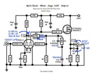
The phono preamp schematic I've uploaded illustrates how it's done. Obviously, the gate is at the same potential as the plate it's tied to. The source sets up a few V. below the gate, but it's OK to ignore that small differential. Select a rational drain current value and use Ohm's Law to compute the source load resistor.
The phono preamp schematic I've uploaded illustrates how it's done. Obviously, the gate is at the same potential as the plate it's tied to. The source sets up a few V. below the gate, but it's OK to ignore that small differential. Select a rational drain current value and use Ohm's Law to compute the source load resistor.
Attachments
- Status
- This old topic is closed. If you want to reopen this topic, contact a moderator using the "Report Post" button.
- Home
- Amplifiers
- Tubes / Valves
- More questions on parallel push-pull