I have WPA 3.5 monoblocks with what appears to be Hammond 270X PT, specked for 620 V CT.
Now, Hammonds are specked for 115V primary voltages and this is where the problem begins - my mains AC reach 124-127 V, transformers get hot, emit mechanical buzz, and, I suspect, their core becomes saturated. Measured HV secondary under load shows 670V CT, filament secondary voltages of 5V and 6.3V also get elevated.
What would be a good PT replacement?
I looked at Edcor XPWR124 as well as their filament transformers and it looks like a viable substitute. XPWR124 is 120V primary and 620VCT 120ma secondary (Hammond is ~80ma).
I'd like Hammond 372X, but everywhere I looked they seem to be factory direct order only with months of lead time and cost 30% than comparable Edcor PT.
Attachments
Last edited:
I have WPA 3.5 monoblocks with what appears to be Hammond 270X PT, specked for 620 V CT.
Now, Hammonds are specked for 115V primary voltages and this is where the problem begins - my mains AC reach 124-127 V,
Not according to the spec. sheet here. There should be a 115V and a 125V tap. Check to see if yours has the two primary taps.
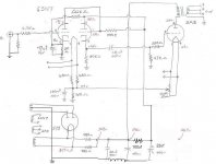
Now, if your power transformer really is a Hammond 270X then the problem becomes clear: that transformer is only rated for 46mA! According to your schematic, the 2A3 alone is drawing 57mA of current; add in the 6SN7s and you are easily drawing 60mA from a transformer rated at 46mA. No wonder it's running hot.
What you need is simply a PT that can provide sufficient current at the desired voltage. However, to select the proper power transformer it would make sense to examine the power supply as it is now and to redesign based on the available power transformers and any enhancements you want to make to it. As it is now the entire power supply is choking your amplifier reducing dynamics and low frequency power.
Ideally, we want 295V on the plate of the 2A3 @ 60mA with a grid bias of -45V. That gives us 250V plate to cathode which is the spec. Assume you lose 5V - 10V in the output transformer means we need roughly 305V at the output of the power supply. You would want a PT capable of 80mA - 100mA.
How you get there depends on how willing you are to modify the power supply. Would you be willing to add a choke and another filter cap? I would definitely suggest you get rid of the two 480 ohm resistors and add a choke and another cap to make it: rectifier -> 40uF -> choke -> 100uf.
The best tool for modeling power supplies is PSUD2 which is freeware. I suggest that you download it and try to model the power supply based on available power transformers and chokes. With a properly designed power supply you can easily take this amp to a higher level of audio quality.
Palustris, thank's for the reply.
I am pretty sure it is Hammond, but exactly which one I am not sure, I think it's 272X which is 620VCT @80ma. The 120V tap was instituted by Hammond in 2009, my amps were assembled on 10/2000, so no 120V tap there. I think Mr. Wright purposely used them there as the operating points seem to be spot on throughout the amp. However, those PT's are not optimal.
I did simulations on PSUD2 and based on them the 330-0-330 V 120ma Edcor shoud be fine as a drop in.
I don't like those 470R resistors either. Late George Wright was using them on, I believe, all of his amps, mostly to prolong the life of rectifier tubes. I may experiment replacing those resistors with 3H input choke - that should give me better regulation and a required voltage drop. Your suggestion of adding another LC filter is also worth considering. In both cases it would change the sound signature of the amp - something I would not like to do.
Currently voltages under load read as follows: PT output - 335V per side, 5Y3 output - 324V, after 470R resistors - 308V, after choke - 296V, after second RC filter - 283V, at the 2A3 plate - 290V, cathode - 43V.
Plate voltage could go up a bit.
Last edited:
You have to forgive me if I get a little carried away with your Wright amp. I am only looking at it on paper as a design exercise. I have no knowledge of the sound signature of a Wright amp, nor can I predict how it will change with a better power supply. A properly engineered power supply will give you a dynamic amp with a black background and the ability to follow complex musical passages easily.
All that said, I didn't see the choke in the schematic. Apparently the choke (that I now see) is in the pos leg not the neg leg as it appears on the schematic and so you already have a CLC power supply. In other words: never mind what I suggested as the power supply is almost exactly as I suggested.
You really should do away with the 470R resistors. This means you probably could use the Edcor XPWR061 600V ct transformer, but model it in PSUD2 first to be sure. This transformer is able to produce 120mA so at the current you will be using it, you will probably get over 300V a side. The XPWR124 will work fine too, but you will get even more voltage. I really like the Hammond 300 series transformers and think they are excellent quality. The Hammond 372BX is about $30 more than the Edcor. A 5R4 rectifier will drop about 25V more than the 5Y3 or 5AR4 if you need to really reduce the supply voltage.
You could design for 300V plate to cathode for the 2A3 and use the JJ 2A3-40 a, very nice tube, and able to handle much more voltage and current than the original. I run mine at 290V @65mA.
A 5R4 rectifier will drop about 25V more than the 5Y3 or 5AR4 if you need to really reduce the supply voltage.
Per mA. of B+ drawn, a 5Y3 drops more than a 5R4. The whopping 67 V. of forward drop in a 5R4 occurs when 250 mA. of B+ are drawn.
A 5 V. rectifier with a larger forward drop than the 5Y3 exists, but I can't recall the type's #.
The choke is indeed on the negative leg, one of the peculiarities of these amps. George explained that having a choke in the negative leg removes massive amounts of DC load from the choke, and this schematic is an "old DIY'ers trick".
Most of the things you mentioned above have been considered many times by many builders.
Here are the limitations and considerations to keep in mind: Resistors after the rectifier perform a certain function and should probably remain. Output transformers are MQ TFA-204 allowing max 70ma DC current, so higher voltages with JJ 2a3-40 may not be an option (it's been tried before). Old 5Y3 will have higher forward drop than 5R4.
I would love to try Hammond 372X, unfortunately not one supplier has them in stock.
As I mentioned earlier my goal is to find a suitable drop in replacement PT. George Wright took Hammond with 115V primary and specked it for 120V mains which makes choosing a modern replacement purely by looking at spec sheets impossible.
Thanks Eli, you are correct. I was going by the numbers above (PT output - 335V per side, 5Y3 output - 324V,), and didn't double check even though it didn't sound correct. The problem is that all the power transformers he is looking at only have 2A rectifier taps, so he is constrained to the 5Y3, 5AR4 and 5R4.
I would love to try Hammond 372X, unfortunately not one supplier has them in stock.
Antique Electric Supply lists them as "in stock."
Generally the 300 series Hammonds are larger for a given rating. Space is already tight on your amp, so better to check the mounting layout dimensions. George switched to Deyoung for the power transformers in later production because of complaints about the Hammond buzzing and running hot.
OK, to eliminate any guesswork I took my Fluke and measured everything again with 8 Ohm resistor on output. Here are the results and they are not good:
Mains AC - 124V
2A3 filaments measured at 2.78 V ac
6SN7 filaments - 7.2 V ac
PT output - 683 V ac
After 470R resistors - 317 V dc
After RC filter - 304 V dc (at the 6SN7 top plate)
at 2A3 plate - 308 V
at cathode - 47 V, so that makes 361 V plate to cathode.
It is obvious to me that 115V trafo should be replaced ASAP as well as 2A3 filament transformer. I am simply destroying my tubes!
Last edited:
Antique Electric Supply lists them as "in stock."
They have 272X which is plentifull, no 372X though...
It is obvious to me that 115V trafo should be replaced ASAP as well as 2A3 filament transformer. I am simply destroying my tubes!
Perhaps it's time to be "creative". A $38.50 AnTek AS-05T280 toroid might get the job done for you. Use 1 of the 6.3 V. windings to energize the heater of a 6BY5 dual damper B+ rectifier. Use the other 6.3 V. winding to power the small signal tube(s).
BFD, if you have to fabricate a bracket on which the toroid mounts.

I replaced PT with Hammond 272BX. These transformers have 115 and 125 V taps on the primary. Direct replacement resulted in the voltage drop that allowed for removal of those 470ohm resistors. All voltages are as per original specs - 250V across 2a3...
2a3 filament transformer was connected to 115V tap (in a bucking fashion) resulting in more or less precise 2.5V AC.
It is a big improvement over the original transformers.
2a3 filament transformer was connected to 115V tap (in a bucking fashion) resulting in more or less precise 2.5V AC.
It is a big improvement over the original transformers.
After running the amps for several hours I sat down and gave it a good listen. The amps now sound "faster" with better attack edges on the bass and better defined highs. Previously these amps sounded a bit colored that could be described as "romantic", now that coloration seems to be gone. Transformers are dead silent and running much cooler.
Extremely happy with modifications.
Extremely happy with modifications.
I have a pair of later amps with the better transformers.
I bought them a few months back, but got no information with them.
So far the I am pretty impressed, but feel like it may be time to try some mods.
Thinking caps maybe first.
From this thread I gather there are no published schematics, it that true?
I bought them a few months back, but got no information with them.
So far the I am pretty impressed, but feel like it may be time to try some mods.
Thinking caps maybe first.
From this thread I gather there are no published schematics, it that true?
I have a pair of later amps with the better transformers.
I bought them a few months back, but got no information with them.
So far the I am pretty impressed, but feel like it may be time to try some mods.
Thinking caps maybe first.
From this thread I gather there are no published schematics, it that true?
Correct, there are no official published schematics of these amps. It is not difficult to reverse engineer and draw your own schematics though - the amps are very simple.
The first thing to replace on these amps are power supply capacitors, chances are they are old (what is the assembly date on the labels on your amps?). Original coupling cap is Orange Drop which could be replaced with something better.
I replaced all caps with good quality ones, and all resistors with Mills and Kiwame. I also installed hum pots.
These are wonderful little amps with some unique design features.
George often used surplus parts, especially the capacitors. I've seen power supply caps on brand new amps that had ten year-old date codes, but they worked fine over the long-term. From what I've seen, early production used mainly Panasonic for the coupling caps, but even here, he sometimes used surplus. George did not believe in boutique parts, although he would put them in if you requested. To me, his gear sounded fine with common industrial parts; one of the things I admired about his designs.
I do find these amps sound quite good running my Lowther open baffle speakers as is. I just keep thinking they are begging for mods and look really simple to work on. P/S caps were my first thought too.
I would say that George was wise not going to deep into the boutique parts thing, its not the dollar amount that gives joy, but the synergy of the parts.
Cheers
Ed
I would say that George was wise not going to deep into the boutique parts thing, its not the dollar amount that gives joy, but the synergy of the parts.
Cheers
Ed
- Status
- This old topic is closed. If you want to reopen this topic, contact a moderator using the "Report Post" button.
- Home
- Amplifiers
- Tubes / Valves
- Wright Sound WPA 3.5 Power Transformer Replacement Options