Hello All,
Im gathering parts to build the jelabs 76 line preamp with out the phono stage and do have questions for the experts: here is the link JE Labs Arkiv: JE Labs phono and line preamp
1) on the power supply schematic it says the B+ voltage is 290 volts but the 76 line amp scheme is only asking for 280v. should I make the power supply voltage 280 volts and forget about the 290V?
2) what is the gain of this preamp? im assuming that since it has a cathode follower output that it has no gain.
3) can i use ac and just elevate the heaters?
thanks,
zach
Hello All,
Im gathering parts to build the jelabs 76 line preamp with out the phono stage and do have questions for the experts: here is the link JE Labs Arkiv: JE Labs phono and line preamp
1) on the power supply schematic it says the B+ voltage is 290 volts but the 76 line amp scheme is only asking for 280v. should I make the power supply voltage 280 volts and forget about the 290V?
2) what is the gain of this preamp? im assuming that since it has a cathode follower output that it has no gain.
3) can i use ac and just elevate the heaters?
thanks,
zach
1) 280 or 290V in the power supply will not make a real difference. If you want to drop those 10V at any rate and have the same identical operational point (assuming that your tubes are identical!) then you can increase the resistance in the filtering. You could stick to the 1.5K+47uF as is and add another RC cell before using a 3.3K or just use one RC filter with 4.7K instead of 1.5K.
2) The gain of the complete amp is about 90% of the single common cathode alone.
3) yes but I would not elevate the voltage to a value equal or greater than the cathode. However DC supply will work better, IMHO.
It's sad to say, but the numbers just don't add up on that schematic. I always re-engineer any schematic before I build as I want to ensure that the design was properly engineered in the first place. In this case there is no operating point that corresponds to Ep = 175V and Eg = -7V. A quick check of the plate curves shows that with a plate voltage of 175V and a plate supply of 280V and 33k load line there is considerable 2nd harmonic distortion at the actual bias point for this load line of about -10V. Notice the schematic gives a bias of -7V. This is not correct.
The 76 needs to be biased properly to work in its linear region and it should be run at about 5mA for best linearity. So we are actually looking for a bias of -4V with a plate voltage of 110V @ 5mA. This requires a change of cathode resistor to 800 ohms. You still need the cathode bypass cap so I would replace the cathode resistor with two LEDs negating the need for the cap. You will have to select the LEDs for a forward drop of about 2 V. The circuit will work fine if the only LEDs you can find have a forward drop of 1.7V, but your plate voltage will be closer to 100V.
The gain of the preamp will be about 10.
How can I use a 76 as a first stage of a PP amp and use a CCS on top and Led(s) at the cathode ? What current through the tube, voltage on the CCS and on the cathode, how many Leds (what colour ?
What does the rest of the circuit look like? That's not enough information. If you are talking about a PP pentode amp, the 76 will probably not provide enough gain to allow feedback in the first stage.
In general, though, you want to set your CCS for 5mA and the bias voltage will depend on your plate voltage and how large a signal you want to amplify. Use the load lines to figure out your operating points.
It's sad to say, but the numbers just don't add up on that schematic. I always re-engineer any schematic before I build as I want to ensure that the design was properly engineered in the first place. In this case there is no operating point that corresponds to Ep = 175V and Eg = -7V. A quick check of the plate curves shows that with a plate voltage of 175V and a plate supply of 280V and 33k load line there is considerable 2nd harmonic distortion at the actual bias point for this load line of about -10V. Notice the schematic gives a bias of -7V. This is not correct.
The 76 needs to be biased properly to work in its linear region and it should be run at about 5mA for best linearity. So we are actually looking for a bias of -4V with a plate voltage of 110V @ 5mA. This requires a change of cathode resistor to 800 ohms. You still need the cathode bypass cap so I would replace the cathode resistor with two LEDs negating the need for the cap. You will have to select the LEDs for a forward drop of about 2 V. The circuit will work fine if the only LEDs you can find have a forward drop of 1.7V, but your plate voltage will be closer to 100V.
The gain of the preamp will be about 10.
In general I agree but you might consider than there is variance around the average curves in the datasheet and those tubes in that schematics could not be new?
Anyway if you take the average specs without modifying the circuit you will get something like 3.6 mA at - 8V bias and just above 150V effective anode voltage. Not very different from about 3.2 mA/168V at - 7V in that schematics. It cannot be -10V with 2.2K self bias resistor and 33K anode load because that would mean about 4.5 mA and 150V voltage drop at the anode resistor leaving just 120V anode voltage. This is not even close to the average curves.
@Palustris - I agree with 45, not sure how you got -10V bias
 Here is what I got with Ep=280V, Rp=33k, looks pretty linear with ~-7V bias.
An externally hosted image should be here but it was not working when we last tested it.
I'm sorry for the confusion. I tried to upload the 76 plate curves to my last post but failed. Here they are:
76 plate curves
I determined the 76 plate current from the JE Labs schematic. 7V / 2.2k = 3.18mA. I plotted the 33k load line with the B+ @ 280V and plate voltage at 175V and the current at 3.1mA. As you can see, the corresponding grid bias is -10V. I hope it's clear now where the -10V comes from (OK, maybe it's -9.5V).
So the next question should be: if 175V @ 3.1mA and -7V is not a valid operating point, what is a valid operating point?
I selected 110V @ 5mA because that is the most linear part of the plate curves for a 33k load line with a 280V B+. You can see the operating point outlined in green with a -4V bias voltage.
Since this is a preamp, the input voltage from the source will be <2 Vp The grid can swing from -2 to -6 in the most linear part of the curves. The output with 2V in will be about 145V - 85V = 60Vpp = 30Vp * .707 = 21.21VRMS * .9 = ~ 20VRMS; way more than necessary to drive any power amp.
I hope this helps.
I'm sorry for the confusion. I tried to upload the 76 plate curves to my last post but failed. Here they are:
76 plate curves
I determined the 76 plate current from the JE Labs schematic. 7V / 2.2k = 3.18mA. I plotted the 33k load line with the B+ @ 280V and plate voltage at 175V and the current at 3.1mA. As you can see, the corresponding grid bias is -10V. I hope it's clear now where the -10V comes from (OK, maybe it's -9.5V).
So the next question should be: if 175V @ 3.1mA and -7V is not a valid operating point, what is a valid operating point?
I selected 110V @ 5mA because that is the most linear part of the plate curves for a 33k load line with a 280V B+. You can see the operating point outlined in green with a -4V bias voltage.
Since this is a preamp, the input voltage from the source will be <2 Vp The grid can swing from -2 to -6 in the most linear part of the curves. The output with 2V in will be about 145V - 85V = 60Vpp = 30Vp * .707 = 21.21VRMS * .9 = ~ 20VRMS; way more than necessary to drive any power amp.
I hope this helps.
I see what you meant now
Yes, there is something not quite right about the voltages shown in the JE Lab schematic - it might be typo and/or they were based on actual measurements from a really odd tube...I'm sorry for the confusion. I tried to upload the 76 plate curves to my last post but failed. Here they are:
76 plate curves
I determined the 76 plate current from the JE Labs schematic. 7V / 2.2k = 3.18mA. I plotted the 33k load line with the B+ @ 280V and plate voltage at 175V and the current at 3.1mA. As you can see, the corresponding grid bias is -10V. I hope it's clear now where the -10V comes from (OK, maybe it's -9.5V).
So the next question should be: if 175V @ 3.1mA and -7V is not a valid operating point, what is a valid operating point?
The plate voltage is measured between the plate and the cathode and so it is 168V. 168V/3.1mA at -7V can be considered valid. It could be because the tube is well used or a tube differing from the average.
In the data-sheet average tube you would get something like 150V/3.6mA at about -8V with 2.2K self bias and 33K.
You cannot have -10V because 10V/2.2K =4.5 mA and this would only leave 120V plate voltage with 33K anode resistor. Your load-line would be fine if you had a fixed independent bias.
Or, using self-bias and 33K anode load, you could get about 170V/3 mA at about -10V with 3.3K cathode resistance or 110V/5mA at -4V with 800R. If you stick to 2.2K cathode resistance and 33K anode load than the only other potential variable you are left with is the supply voltage. If the supply is also fixed you can't get -10V.
Hello All,
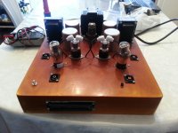
I just finished the preamp. It's dynamic and transparent. Will get a handle on how I will like it with more time,but so far I lIKE it. Thanks to all who helped, it is very much appreciated. May you all be blessed
I just finished the preamp. It's dynamic and transparent. Will get a handle on how I will like it with more time,but so far I lIKE it. Thanks to all who helped, it is very much appreciated. May you all be blessed
Attachments
The plate voltage is measured between the plate and the cathode and so it is 168V. 168V/3.1mA at -7V can be considered valid. It could be because the tube is well used or a tube differing from the average.
In the data-sheet average tube you would get something like 150V/3.6mA at about -8V with 2.2K self bias and 33K.
You cannot have -10V because 10V/2.2K =4.5 mA and this would only leave 120V plate voltage with 33K anode resistor. Your load-line would be fine if you had a fixed independent bias.
This is correct. The figures in the JE circuits are the actual 'life' measurements of the final working circuits and is in the context of the tolerances of the components and valves when the measurements were taken. (Examples of 76 that would test like it plots is not as easy to get hold of eventhough there are plenty of valves themselves. This is why he recommends using a 6sn7 in his dx circuits if good quality 76 cannot be found.) This also accounts for the 10v difference mentioned between the two schematics as different circuit variations and valves were tested concurrently. His circuits were not simulated or modelled, rather, he built his breadboards and prototypes listened and measured. This is why he mentions the caveat that his circuits are in the context of his system at the time they were developed and the choices for operating points he made are based on his own personal preferences regardless of 'textbook wisdom'.
I've built this preamp twice. The first using 6sn7 on the preamp stage in line with the very first iteration of this circuit. But I also made a socket adaptor to try the 76 after which I built the 76 version. The above was gleaned asking JE himself about certain details of the circuits (I've also built a 2a3dx) of his that I've built.
Zgondouin, congratulations on your build. I too am enjoying the circuit.
- Status
- This old topic is closed. If you want to reopen this topic, contact a moderator using the "Report Post" button.
- Home
- Amplifiers
- Tubes / Valves
- je labs type 76 preamp build!