Hi,
I'm hoping for some help in understanding the following situation.
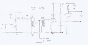
If the inductive reactance of the S&B102mk3 primary is ~100kohm at 20Hz and drives a 1:4 step up transformer which is loaded by open grid to ground of a triode in parallel with 10M, I can see the reflected impedance across the stepup transformer will be 1/16th of 10M//open grid.
Can I assume open grid to ground of triode to be infinite and therefore calculate the 102mk3 to be loaded by 10M/16 = 625k ?
Working with worst case scenario, with zero attenuation and 1:1 TVC, is it Xl of the TVC that then fully determines the impedance that the capacitor works into?
With some attenuation at the TVC, say 4:1, the reflected impedance would be 625k x 16 = 10M.. but it is still the inductive reactance of the TVC primary that determines the impedance that the capacitor works into, it stays at 100kohm at 20Hz, and the 10M load has no bearing on Cx calculations, just re-affirms a suitably high load to the secondary?
If I understand this correctly (and that is the real question), a nice 0.22 - 0.47uF capacitor would suit well..
Any comment appreciated,
Shane
I'm hoping for some help in understanding the following situation.
If the inductive reactance of the S&B102mk3 primary is ~100kohm at 20Hz and drives a 1:4 step up transformer which is loaded by open grid to ground of a triode in parallel with 10M, I can see the reflected impedance across the stepup transformer will be 1/16th of 10M//open grid.
Can I assume open grid to ground of triode to be infinite and therefore calculate the 102mk3 to be loaded by 10M/16 = 625k ?
Working with worst case scenario, with zero attenuation and 1:1 TVC, is it Xl of the TVC that then fully determines the impedance that the capacitor works into?
With some attenuation at the TVC, say 4:1, the reflected impedance would be 625k x 16 = 10M.. but it is still the inductive reactance of the TVC primary that determines the impedance that the capacitor works into, it stays at 100kohm at 20Hz, and the 10M load has no bearing on Cx calculations, just re-affirms a suitably high load to the secondary?
If I understand this correctly (and that is the real question), a nice 0.22 - 0.47uF capacitor would suit well..
Any comment appreciated,
Shane
Attachments
What you haven't accounted for is the high probability of resonances which will need damping. Almost all transformers have self resonance where the capacitive losses form a tank with the inductance. The easiest way to solve this is to load the secondary down with a resistor (often of a quite low value) which would make all your calculations mute.
The difficult way to damp the resonances is with a zobel - which has to be tuned for thew exact circuit the transformer is used in. This is a matter of trial and error.
In short - you can make what you plan work - but don't expect it to be as easy as the raw impedances would suggest.
Shoog
The difficult way to damp the resonances is with a zobel - which has to be tuned for thew exact circuit the transformer is used in. This is a matter of trial and error.
In short - you can make what you plan work - but don't expect it to be as easy as the raw impedances would suggest.
Shoog
A valve grid could have a DC/LF impedance in the M or 10's of M region, mainly resistive (due to grid current). The impedance at 20kHz could be much smaller, but capacitive due to Miller effect.
Transformers have leakage inductance and stray capacitance, so using them at impedances far removed from what they were designed for means they no longer act as simple wideband impedance transforming devices.
Transformers have leakage inductance and stray capacitance, so using them at impedances far removed from what they were designed for means they no longer act as simple wideband impedance transforming devices.
Thanks Shoog, I'm not so after square wave performance but rather good sound, I'm sure you know what I mean. I use an SE to PP interstage for the main amplifier - and it measures better but sounds worse when loaded down.
Thanks, DF96. Would you think the capacitive effects on BW might be limited somewhat when driven by ~200ohms?. - So far as impedances far from what they are designed for; I'm not fully realising the point that is being put forward: the TVC is driven and (presumably) loaded as it would like to be, and the 1:4 acts as an impedance matching device (voltage gain aside), driven low Z and loaded high Z - all within what might be considered within the means of what they were designed for. (??)
Thanks, DF96. Would you think the capacitive effects on BW might be limited somewhat when driven by ~200ohms?. - So far as impedances far from what they are designed for; I'm not fully realising the point that is being put forward: the TVC is driven and (presumably) loaded as it would like to be, and the 1:4 acts as an impedance matching device (voltage gain aside), driven low Z and loaded high Z - all within what might be considered within the means of what they were designed for. (??)
Hi!
The LL7903 needs low impedance drive to work best. I usually drive it with impedances well below 500 Ohms. The size of that coupling cap will surely play a role. If you have the parts in hand, try it and measure and adapt as necessary. The LL7903 will have some ringing if lightly loaded.
Best regards
Thomas
Hi!
The LL7903 needs low impedance drive to work best. I usually drive it with impedances well below 500 Ohms. The size of that coupling cap will surely play a role. If you have the parts in hand, try it and measure and adapt as necessary. The LL7903 will have some ringing if lightly loaded.
Best regards
Thomas
Hi Thomas,
I was thinking the drive impedance to the LL7903 in this case would be 200 ohms with zero attenuation at the TVC, and less when attenuated. (say TVC at position 2:1, 200/4 = 50 ohm drive to LL7903)...
Your mention of the cap with regard to this has me thinking.. is the Xc of the cap at a given frequency added directly to the drive impedance, or does phase shift come in to play so that the total is not simply the sum of drive impedance + Xc ?.
Have you found the ringing to be a problem?, IIRC your schematics show the LL7903 with the secondary loaded in the same manner.
Regards,
Shane
When driving a stiff load from the MU output of a CCS it can help to add either a resistor or a CCS to ground from the MU output. The resistor or CCS increases the bias current in the main CCS. This makes more current available to drive the load, especially at high frequencies where the miller capacitance of the next stage becomes dominant.
The MU output of a CCS has a quite asymmetrical drive capability with large amounts of current available to drive loads in the positive direction but is limited to the bias current of the vacuum tube under the CCS when driving in the negative direction. The extra load on the MU output increases the drive capability when the signal swings in the negative direction.
The MU output of a CCS has a quite asymmetrical drive capability with large amounts of current available to drive loads in the positive direction but is limited to the bias current of the vacuum tube under the CCS when driving in the negative direction. The extra load on the MU output increases the drive capability when the signal swings in the negative direction.
Hi!
Yes
You will get some resonance peaks at low frequency depending on cap size.
Best to measure and see whats going on
No, but some people mind the ringing
Best regards
Thomas
is the Xc of the cap at a given frequency added directly to the drive impedance,
Yes
or does phase shift come in to play so that the total is not simply the sum of drive impedance + Xc ?.
You will get some resonance peaks at low frequency depending on cap size.
Best to measure and see whats going on
Have you found the ringing to be a problem?,
No, but some people mind the ringing
Best regards
Thomas
The LL7903 needs low impedance drive to work best. I usually drive it with impedances well below 500 Ohms.
At what frequency would you recommend the drive impedance be less than 500 ohm? The LL7903 and the main amplifier drive a loudspeaker which has a LF that rolls off at ~50Hz.
With 4.7uF, total drive then should be (338 + 200) 538 ohms at 100Hz. Of course the Xc increasing inversely proportional to frequency.
4.7uF
20Hz = 1693ohm
50Hz = 677 ohm
100Hz = 338 ohm
2.2uF
20Hz = 3617 ohm
50Hz = 1446 ohm
100Hz = 723 ohm
You will get some resonance peaks at low frequency depending on cap size.
Best to measure and see whats going on
If the primary inductance of the S&B TX-102 is 400H at 20Hz, resonance with 2.2uF would be at approx 6Hz, and 3.6Hz with 4.7uF.
Neither resonance or LF pole seem to be a problem. It might be coming down to the increase the Xc has on drive impedance to the LL7903, in which case I might find needing to compromise between suitable drive impedance and the cost/size of the coupling capacitor.
Getting closer.
Regards,
Shane
Last edited:
When driving a stiff load from the MU output of a CCS it can help to add either a resistor or a CCS to ground from the MU output. The resistor or CCS increases the bias current in the main CCS. This makes more current available to drive the load, especially at high frequencies where the miller capacitance of the next stage becomes dominant.
Thanks, Gary.
These CCS are your rev5 self biased ccts, I've two more which I can try as you suggest. Plate voltage is ~65V, in the event that its not enough, I can try the resistor, but hopefully it'll hold.
The CCS that you used with 26 DC 300B at Gary Pimm's DIY audio pages , can I ask how you arrived at the 9mA value, was is proportional to the plate current of the 26 triode, or just a suitable value. Additionally, with the signal from the Mu output, is the plate load CCS supplying also the full additional current of the shunt CCS?.
And lastly, if I can, you mention as part of the 47PP write-up at Gary Pimm's DIY audio pages that you were using an AVC to drive LL1676. Can I ask what value coupling capacitor you were using and also the primary inductance of the AVC?.
Again, Thanks.
Shane
Last edited:
At what frequency would you recommend the drive impedance be less than 500 ohm?
Over the frequencies you would like to cover...
The inductance of the 7903 will be in parallel to that of the TVC and it will be different for each volume setting.
Again: Try and measure and listen ...
Thomas
Over the frequencies you would like to cover...
The inductance of the 7903 will be in parallel to that of the TVC and it will be different for each volume setting.
Again: Try and measure and listen ...
Thomas
Thanks, Thomas.
Thanks, Gary.
These CCS are your rev5 self biased ccts, I've two more which I can try as you suggest. Plate voltage is ~65V, in the event that its not enough, I can try the resistor, but hopefully it'll hold.
The CCS that you used with 26 DC 300B at Gary Pimm's DIY audio pages , can I ask how you arrived at the 9mA value, was is proportional to the plate current of the 26 triode, or just a suitable value. Additionally, with the signal from the Mu output, is the plate load CCS supplying also the full additional current of the shunt CCS?.
And lastly, if I can, you mention as part of the 47PP write-up at Gary Pimm's DIY audio pages that you were using an AVC to drive LL1676. Can I ask what value coupling capacitor you were using and also the primary inductance of the AVC?.
Again, Thanks.
Shane
As far as why 9ma was chosen I couldn't tell you now... That was 11 years ago. It was probably chosen as a compromise of current boost vs power loss in the CCS feeding the VR tubes.
Yes, the plate load CCS was supplying all the current for both the plate of the 26 and the current boost CCS
What tube are you using for the input stage? 65 volts does not sound like much. What signal level are you going to see on the plate of the input tube? What is the B+ above the CCS?
The first SE AVC was driven from a couple of different sources. At that time the main sources were a Pioneer DV563 with Sowter 10K bridging transformers connected directly to the DAC or the my phono preamp with 3uf to 4uf caps driven from the mu output of the second stage into 4:1 step down transformers.
The single ended AVC was a Dave Slagle design. I don't know what the primary impedance was as I don't have that unit any longer.
The second AVC was a balanced unit built using 2 Slagle auto-transfomers mounted face to face per channel. That unit measures 31Hy primary inductance. The balanced unit was driven either from the phono preamp or directly from the DAC in the Pioneer DV563. At the time the balanced AVC was in use all the power amplifiers were balanced so the 2.5Vdc offset of the DAC did not matter.
Hope this helps.
What tube are you using for the input stage? 65 volts does not sound like much. What signal level are you going to see on the plate of the input tube? What is the B+ above the CCS?
The first SE AVC was driven from a couple of different sources. At that time the main sources were a Pioneer DV563 with Sowter 10K bridging transformers connected directly to the DAC or the my phono preamp with 3uf to 4uf caps driven from the mu output of the second stage into 4:1 step down transformers.
Hi Gary,
The input stage is the I/V of the DAC, 6922 biased by 4mAp-p Iout through 33ohm grid leak. Ip 12mA. B supply is 250V. Maximum signal at plate would be approx 4vp-p.
In light of recent comments, the setup with the 4uF into the step-down as you had it makes sense to me, the Xc of the cap at LF is reduced ~16 times. I should probably use a higher gain tube and step down with the TVC. As it is, gain structure as it is is about right for zero attenuation with the lowest recorded material at the loudest playback levels. I can get a bit more than twice the drive level with D3A as a triode.
If I understand correctly, the shunt CCS will have less positive effect with tubes that set up at higher plate current, and depending on the capacities that it drives (100pF for the TX-102 primary) it might not be necessary with Ip 10mA+.
Having some 6SL7 and 6072A to use at <3mA, I would like to ask if there is any meaningful difference between using the shunt/boost CCS and a simple resistor?
Regards,
Shane
With an expected signal level of 4Vp-p the plate voltage is fine. I was visualizing a much higher signal...
Personally, I think you are on the right track going for more gain in the first stage and loosing the step up transformer after the TVC. While step up transformers look good on paper, driving them successfully in the real world is difficult.
You are correct in thinking that the boost CCS/resistor will not have as much effect in a higher current configuration.
As for using a CCS or resistor for the current boost I've done it both ways. In one instance the resistor had lower distortion than a CCS. I suspect that having the current through the source follower varying with the signal was canceling some of the distortion of the triode under the CCS. In the active 300B I used CCSs because I had a pile of them and it was an excuse to use yet another one in the amp...
Gary
Thanks, Gary.
I'll try the higher mu tube up front, and use more attenuation at the TVC to get some stepdown to help lower drive impedance and keep the value of the coupling C at something reasonable, use the simple resistor as boost for tubes that set up at lower currents, and leave the CCS at 10mA -12mA total.
The 1:4 step up is at the input of the main amplifier the first stage and TVC are part of the D/A unit. The stepup has the gain balance between main and LF amplifiers about right and isolates the -150V at its secondary from the input.
Time to start measuring effects on LF response at the input to the step up with values of coupling C and go from there.
Regards,
Shane
Using resonance and a fixed value for Cx, the inductance of the S&B (AVC) in parallel with the LL7903 is 44H.
Thanks to the nice chap who linked me to the excellent site regarding LF peaking and 'lossy parafeed', 2.2uF//9.4uF+2700 has things essentially flat to way down in single digit Hz and the Cx combining with Zout of the tube stage has drive impedance below 500 ohm at all usable frequencies using 33R I/V and D3A, allowing for some step down.
Sounds great.
Regards,
Shane
- Status
- This old topic is closed. If you want to reopen this topic, contact a moderator using the "Report Post" button.
- Home
- Amplifiers
- Tubes / Valves
- Q: Cascaded Transformers, S&B102+LL7903