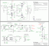
I have built the amplifier in the schematic below. After a great many troubleshootings including blown poor quality caps i got it to be noise free and working. Just a little pop sound every now and again at least until the tubes heat up. I noticed the pops are at the same time when the tubes chime as elements move due to normal heating.
The real problem is, it works, but it's rather dull, not chimy as some suggest EL84's would usually be, and the bass notes are a bit undefined and monotonous. Below is also part of the power supply. The EL84's are at 23mA plate current (almost 70% dissipation) while the phase splitter tubes run at about 1.2mA current (seems little but at that setting when i was using them as preamps they were very lively sounding). Below is also the filtering part of the power supply. Before you ask, no, that is not a regulator, it's just meant to drop voltage while still being stiffer than a plain resistor. (it also has a bonus of added filtering of ripple).
Perhaps you people can help me improve it, especially since i only built this for personal enjoyment no commercially...
http://s16.postimg.org/noqy09f8l/RAMP_schem.jpg
http://s14.postimg.org/81cwi35xd/sursarad.jpg
Is this supposed to be a guitar amp? If it's meant for hifi, I'd wait until the rookie has a few years in the league before trying to build another one of his designs. Zero feedback pentode is unlikely to get you good sound with conventional speakers- the source Z is probably in the neighborhood of 50 ohms, and bass distortion from driving the transformer with a high impedance could be north of 10%. The power supply is likely to cause noise issues from the extremely high charging currents at the input cap. The inverter has its tail bypassed.for reasons that are unclear.
As a guitar amp, it may work OK, but building in some power supply sag could be beneficial.
As a guitar amp, it may work OK, but building in some power supply sag could be beneficial.
Hi,
This is not very typical... I hope you are using it as guitar amp, not for audio...
You could get more sparkle with some "bright caps" - 200 pf or so over the tonestack and "gain" potentiometers, and reduce the 100µ cathode bypass on the first stage to 2-5µ.
edit: I posted before seeing SY's answer.
Thanks for the reply. So i am to understand supply sag IS actually bad for a general use amp (not instrument). The tone control would suggest guitar amp but at the lowest position of the pots it's actually almost completely linear. It is as if the correction has only boost and no cut along the entire pot span. It's a modified Marshall type control, as you can see.
I opted for a no feedback amp since i read many people do not use feedback, they prefer to let the tubes do what they want... as it turns out it may be bad after all (at least in pentode mode). I can easily add feedback and i think i'll try it today and see what it does if i'll love it or hate it even more. Although with paraphase it can be tricky, there all sorts of phase shifts due to capacitors etc. Of course i could try something different, adding feedback through the volume potentiometer "ground" pins as it was done a great many years ago.
I just noticed the inverter tail bypass issue. I will remove the bypass as it provides very little extra gain. I had done that since as far as i could find about this inverter type, not having bypassed could insert a minute amount of positive feedback,,, which is always a bad thing and i've never seen so far a controlled positive feedback.
Actually the problem was designing it around what i had available, not as it should be.
Last edited:
There are many tried and true el84 pp amps an this site.
Red light district
Oddwatt el84 pp
Baby huey
Tubelab simple pp
Tubecad journal (john broskie)
I built one that is basically the broskie circuit with a few tweaks from other amps like a CCS on the el84's cathodes for fixed bias current and using a non bypassed red led on the 6n1p. It is a fine little amp with big sound and strong bass.
http://www.diyaudio.com/forums/tubes-valves/171386-anyone-ever-made-el84-p-p-circuit-referenced-tubecad-journal-site.html. Here is part of my journey.
Last edited:
Thanks for the simple and nice schematics. I suppose sound quality comes first and i must confess i had been infected by a more experienced builder who managed as much as 40 (!) watts out of a pair of russian EL84 and that was the recipe, high plate voltage, low-ish screen voltage to prevent burning, moderate plate current leaving room for more swing. As i can tell that was a clas AB2, a different beast altogether so it was pointless incorporating any of those ideas into my amplifier. Although he does say he used a simple split load inverter (don't know how that could drive the output tubes that far) i'm not so sure...
Power and pleasant sound i guess one can't have both, so i'll just settle for quality sound and use one of your schematics, still deciding which one.
Power and pleasant sound i guess one can't have both, so i'll just settle for quality sound and use one of your schematics, still deciding which one.
Power and pleasant sound i guess one can't have both...
Au contraire.
With 450V anode, 250V (approximately) screen on JJ EL84, approximately 25mA/tube idle current, I'm getting about 25 watts out at low distortion, and the amp runs quite cool. Perhaps it could be pushed to about 2dB more output (hardly noticeable), but for 40W, there are much better output tube choices.
So that basically means... you are operating in class A? That 25mA is just about there. I do think you wouldn't be using it if it sounded bad so i believe you. Others did suggest my quiescent current is way too low then i asked "way too low for what?". I'm a little confused as to what is considered safe area of operation for these tubes, since if 70% dissipation (in theory that's where they are currently) is way too cold. They sure can take some abuse, they're not new manufacture, they're 1970 Tungsram, but that doesn't mean they'll have their usual lifespan. I suppose going to class A and adding global NFB would greatly improve things, perhaps i'll do just that.
No, very much AB1. AB2 requires a source or cathode follower before the output tubes, and in this case the extra complication might get me 1-2dB more level. Class A would require much lower plate and screen voltage and higher current- figure 5-6 watts on a good day.
Remember, idle current, power, and class of operation also depend strongly on the anode-to-anode impedance!
Remember, idle current, power, and class of operation also depend strongly on the anode-to-anode impedance!
This is invaluable information indeed. That pretty much means that "recommended" operating conditions that can be easily found on the web are rubbish more or less. Or perhaps they are for guitar amps, but a.f.a.i.k. guitar amps tend to be hot rather than cold biased. It is true, your screen voltage is rather low so that might account for the results. Or i might be missing the point altogether. It would be foolish of me not to listen to the moderator anyway.
Either way, i think i should probably add at least a minimum of NFB.
That all means the best bet is just to design the output stages the classic way, with the actual response curves and load line.
I did get the feedback a number of times that my cathode resistors are too great value so now i got to thinking if smaller ones don't necessarily mean a much larger current but instead i can also modify the screen voltage.
Bloodmist,
B+ sag is BAD, in a HIFI amp. What's required is something with decent regulation, reserves of current, and a low impedance. There are quite a few ways to achieve those goals.
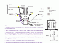
Since you are talking EL84s, I've uploaded "El Cheapo". To use EL84s in the setup, the O/P tube RC bias network has to change. The values shown in the graphic are for 6V6 family tubes.
B+ sag is BAD, in a HIFI amp. What's required is something with decent regulation, reserves of current, and a low impedance. There are quite a few ways to achieve those goals.
Since you are talking EL84s, I've uploaded "El Cheapo". To use EL84s in the setup, the O/P tube RC bias network has to change. The values shown in the graphic are for 6V6 family tubes.
Attachments
As a side note, "moderator" just means that I act as a janitor here- it has no bearing on what I know and don't know.
In any case, guitar amps tend to be run rather cold for max power and a certain "sound." For hifi use, I would follow the datasheet recommendations (Mullard's is particularly comprehensive) until I had enough experience to start breaking the rules deliberately.
In any case, guitar amps tend to be run rather cold for max power and a certain "sound." For hifi use, I would follow the datasheet recommendations (Mullard's is particularly comprehensive) until I had enough experience to start breaking the rules deliberately.
Eli that is really a nice schematic, and i'll give it a go if i find those transistors ")
Clearly there was a problem with mine and trying to make it more lively by cooking the tubes a bit more would not be very nice, as it would result in this:
http://s16.postimg.org/3txynr0th/rausaubun.jpg
And any tube literate around here knows that's not so good news, even though that impedance 8K i used in the graph is hardly a constant.
Eli that is really a nice schematic, and i'll give it a go if i find those transistors
That cascoded FET constant current sink (CCS) was worked out by Doug Piccard, AKA Bandersnatch. Any high quality current sink in the tail of the splitter/driver will do. You might get away with just a 10M45S integrated circuit.
If decent O/P "iron" (instead of the guitar amp stuff shown) is employed, ultra-linear mode "finals" are OK. Triode mode power O/P is approx. 6 WPC and UL mode yields about 12 WPC. IMO, building with good O/P "iron" and UL/triode mode switches makes lots of sense.
Both the Triad N-77U and a Triad VPS24-1800T, for "12" V. heater power and B+ boost, have dual primaries. That makes them suitable in both "120" and "240" V. power mains zones. A Triad C-24X will take care of the PSU filter choke. The little Allied power transformer that energizes the B- supply works only in North America. An EU builder needs to work around that stumbling block.
Attachments
Last edited:
Problem is solved now thanks to fixed biasing - the amp is more responsive. If i see it still presents a too high impedance and distorts at higher power i will also use global NFB although that will be tricky as the output transformers are not factory made such as Hammond and the likes so i'll have to go hit-and miss.
Thanks for all your pertinent advice!
Thanks for all your pertinent advice!
In keeping with my tradition of always forgetting one question, i'd like to ask:
I have 2 options right now since together with the preamp there is too much gain. As such what is best? More power amplifier gain and more global NFB or less gain and less global NFB? The general consensus seems to be that the open loop gain must be high-ish in order for the feedback not to introduce too much high order harmonics, not to mention IMD.
Currently i have about 2 choices for instance while maintaining the same ratio of NFB: a gain of about 42 or a gain of around 24 (open loop), and i can adjust the feedback ratio accordingly. In a simulation there seems to be little high order harmonics in either configuration, at least until the output tubes start compressing.
Edit: the closed loop gain would be about 13 as i did not want to overdo the feedback, some told me even that could be too little feedback.
Last edited:
I'd like to edit the previous but since that's not possible i'll risk ban or whatever gives and triple post...
I really need help... really really. I built the final version of the amp below. And it sounds breathtakingly beautiful but... after a while there appears a very high pitched barely perceptible squeal i don't know where it comes from it's not the speakers... it's either the OT's or the output tubes themselves. At one point the strange noise became louder so in fear of destroying the amp i turned it off.
I measured the voltages, they don't change, nor does the bias voltage. I don't have a scope to find out what happens beyond human hearing i removed all tubes but the EL84's and the squeak still appears after a while. I added a zobel network on the output and nothing changes. Again, i must add, the sound quality never changes while this strange squeak appears so i don't know what i'm doing wrong... please any idea would be apreciated. I don't think i have the time or morale to dismantle it and start from scratch and i think since it seems to produce a great sound it hopefully won't be necessary.
http://s22.postimg.org/cl709xou9/amp_2.jpg
Edit: the strange sound dissapears of course when i flip the standby switch so it's definitely not a resonance in the casing or anything.
I really need help... really really. I built the final version of the amp below. And it sounds breathtakingly beautiful but... after a while there appears a very high pitched barely perceptible squeal i don't know where it comes from it's not the speakers... it's either the OT's or the output tubes themselves. At one point the strange noise became louder so in fear of destroying the amp i turned it off.
I measured the voltages, they don't change, nor does the bias voltage. I don't have a scope to find out what happens beyond human hearing
i removed all tubes but the EL84's and the squeak still appears after a while. I added a zobel network on the output and nothing changes. Again, i must add, the sound quality never changes while this strange squeak appears so i don't know what i'm doing wrong... please any idea would be apreciated. I don't think i have the time or morale to dismantle it and start from scratch and i think since it seems to produce a great sound it hopefully won't be necessary.http://s22.postimg.org/cl709xou9/amp_2.jpg
Edit: the strange sound dissapears of course when i flip the standby switch so it's definitely not a resonance in the casing or anything.
Last edited:
- Status
- This old topic is closed. If you want to reopen this topic, contact a moderator using the "Report Post" button.
- Home
- Amplifiers
- Tubes / Valves
- EL84 "typical" amplifier