i just completed the GEC 88-50 (as shown here: http://www.diyaudio.com/forums/tubes-valves/134364-morgan-jones-kt88-pp-2.html)
and it seemed to have imbalance in the cathode voltages. on one side i have 48/53 volts and on the other side its 48/49 volts. the B+ is 500V. from the drawing i have changed the original 525 ohms cathode resistor to 545 ohms due to availability.
can someone help me here as to how calibrate the cathode voltages to be equal on every side. thks very much")
and it seemed to have imbalance in the cathode voltages. on one side i have 48/53 volts and on the other side its 48/49 volts. the B+ is 500V. from the drawing i have changed the original 525 ohms cathode resistor to 545 ohms due to availability.
can someone help me here as to how calibrate the cathode voltages to be equal on every side. thks very much
I suspect you are just at the mercy of how well matched the valves are in this case. Its self biasing, relying on the high value of cathode resistor to achieve that function. To allow for adjustment would require a separate adjustable negative bias supply for each of the valves and to then also run them with a much lower cathode resistor.
the cathode resistors i used was exactly value matched as i got a bunch of them, baked and measured before choosing the values.
also on the phase splitter cct, i omitted the 25k pot for a fixed value of 47k in the B+ line. what is the function of that 25k pot? is that by any chance intended to correct the imbalance on the next stage?...the driver. im using 6550s.
i've also swapped places for the 6550 with not too good results. just want to get cathode bias right before jumping into fixed biased solutions.
cheers
Attachments
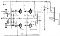
The 25k pot balances the gain so that the output signal of each side of the phase splitter is equal.
As for the cathode voltages on the output stage, I'd be more concerned about the plate current being balanced. You can substitute a pot for one of the cathode resistors in order to obtain a balance. Or, you could replace both cathode resistors with a single 1k pot (plus two 25 ohm resistors) with the wiper grounded and the outer ends connected through the 25 ohm resistors to the cathodes.
As for the cathode voltages on the output stage, I'd be more concerned about the plate current being balanced. You can substitute a pot for one of the cathode resistors in order to obtain a balance. Or, you could replace both cathode resistors with a single 1k pot (plus two 25 ohm resistors) with the wiper grounded and the outer ends connected through the 25 ohm resistors to the cathodes.
Correct, the pot would have to be rated for that amount of power (wirewound). A standard 1k pot would burn up. Actually, the pot wouldn't need to be 1k. A smaller value like 250 ohms would should give enough range of adjustment (and wouldn't have to dissipate as much power), and then the fixed values could be increased to 400 ohms each, which would still give a total resistance between the cathodes of 1050 ohms. As funk1980 says, it may be simpler just to try different fixed resistor values.
- Status
- This old topic is closed. If you want to reopen this topic, contact a moderator using the "Report Post" button.
- Home
- Amplifiers
- Tubes / Valves
- cathode bias imbalance