There were some updates to the library, but Ayumi always used 2008 as the year for the copyright date. I just use the Find and Replace function in the text editor whenever I need to use the Ayumi model in LTspice, i.e., on an as-needed basis, I never bothered to convert all the models.
To change the suffix in Windows, you need to change the file view option under File Explorer, un-check the Hide Commonly Known File Type, then you should be able to make the change.
To change the suffix in Windows, you need to change the file view option under File Explorer, un-check the Hide Commonly Known File Type, then you should be able to make the change.
Thanks for coming back so quickly !
I agree it's probably not a big deal to edit the necessary files each time you're doing a new circuit.
On the file extension, that worked, I found it but I'll put down a bit more detail for anyone landing on the subject again :
With view of folder in Explorer :
Top line 'Organise'
Drop-down 'Folder and Search options'
'View' Tab
Untick 'Hide extensions for known file types'
Click on file and rename extension.
I found it anyway.
1. unzip the attachement
2. Update the location for modelDir in the code to point to your model directory.
3. install python 2.7.X from:
Python Releases for Windows | Python.org
(It'll probably work in 3.x as well)
4. I think you can just double-click the script to run it in the python interpreter (providing it's saved with a .py extension) failing that give me a shout.
5. ???
6. Profit
Code:
import os

modelDir = r'C:\Workarea\Stuff\Valve\LTspiceIV\Ayumi'

for filename in os.listdir(modelDir):
    if filename[-4:] =='.inc':
        incfile = os.path.join(modelDir,filename)
        print('processing: ' + incfile)
        newfile = incfile + '.new'
        with open(newfile, 'w') as outfile, open(incfile, 'r') as infile:
            if newfile:
                for line in infile:
                    newline = line.replace('^', '**')
                    outfile.write(newline)
        os.remove(incfile)
        os.rename(newfile, incfile)
Attachments
I am very interested in your 814&814t. Can you convert the format to LTSPICE? Thank you.In addition to Ayumi's SPICE models, I have generated following
18 models by Ayumi's method.
814 SPICE Model
Here is the LTspice version:
For triode, just connect it as one in the schematic.
Here is the LTspice version:
Code:
*
* Generic pentode model: 814_AN
* Copyright 2003--2008 by Ayumi Nakabayashi, All rights reserved.
* Version 3.10, Generated on Mon Apr 21 13:14:11 2014
*              Plate
*              | Screen Grid
*              | |  Control Grid
*              | |  |  Cathode
*              | |  |  |
.SUBCKT 814_AN A G2 G1 K
BGG   GG   0 V=V(G1,K)+0.99999999
BM1   M1   0 V=(0.049912267*(URAMP(V(G2,K))+1e-10))**-0.68443184
BM2   M2   0 V=(0.68667741*(URAMP(V(GG)+URAMP(V(G2,K))/6.2774666)))**2.1844318
BP    P    0 V=0.00055231093*(URAMP(V(GG)+URAMP(V(G2,K))/9.1417986))**1.5
BIK   IK   0 V=U(V(GG))*V(P)+(1-U(V(GG)))*0.00032281665*V(M1)*V(M2)
BIG   IG   0 V=0.00027615547*URAMP(V(G1,K))**1.5*(URAMP(V(G1,K))/(URAMP(V(A,K))+URAMP(V(G1,K)))*1.2+0.4)
BIK2  IK2  0 V=V(IK,IG)*(1-0.4*(EXP(-URAMP(V(A,K))/URAMP(V(G2,K))*15)-EXP(-15)))
BIG2T IG2T 0 V=V(IK2)*(0.89602099*(1-URAMP(V(A,K))/(URAMP(V(A,K))+10))**1.5+0.10397901)
BIK3  IK3  0 V=V(IK2)*(URAMP(V(A,K))+30300)/(URAMP(V(G2,K))+30300)
BIK4  IK4  0 V=V(IK3)-URAMP(V(IK3)-(0.00036921433*(URAMP(V(A,K))+URAMP(URAMP(V(G2,K))-URAMP(V(A,K))))**1.5))
BIP   IP   0 V=URAMP(V(IK4,IG2T)-URAMP(V(IK4,IG2T)-(0.00036921433*URAMP(V(A,K))**1.5)))
BIAK  A    K I=V(IP)+1e-10*V(A,K)
BIG2  G2   K I=URAMP(V(IK4,IP))
BIGK  G1   K I=V(IG)
* CAPS
CGA   G1  A  0.15p
CGK   G1  K  8.4p
C12   G1  G2 5.6p
CAK   A   K  14p
.ENDS
For triode, just connect it as one in the schematic.
Does anyone have a SPICE model for the RS1003 - Pentode?
Maybe this model is good, we made an SE with RS1003 and the actual measurements were ~ 95% like those in the simulation, try it!
*******************************
*RS1003 idem SRS551
*Vg2=400V
.SUBCKT RS1003 1 4 2 3 ; P G2 G1 K (PENTODE)
.PARAMS: MU= 23.412 EX= 1.315 KG1= 245 KP= 92.4 KG2= 2843 KVB= 80.7 CCG=23P CPG1=0.15P CCP=13P RGI=1K;
RE1 7 0 1G ; DUMMY SO NODE 7 HAS 2 CONNECTIONS
E1 7 0 VALUE={V(4,3)/KP*LOG(1+EXP((1/MU+V(2,3)/V(4,3))*KP))} ; E1 BREAKS UP LONG EQUATION FOR G1.
G1 1 3 VALUE={(PWR(V(7),EX)+PWRS(V(7),EX))/KG1*ATAN(V(1,3)/KVB)}
G2 4 3 VALUE={(EXP(EX*(LOG((V(4,3)/MU)+V(2,3)))))/KG2}
RCP 1 3 1G ; FOR CONVERGENCE
C1 2 3 {CCG} ; CATHODE-GRID 1
C2 1 2 {CPG1} ; GRID 1-PLATE
C3 1 3 {CCP} ; CATHODE-PLATE
R1 2 5 {RGI} ; FOR GRID CURRENT
D3 5 3 DX ; FOR GRID CURRENT
.MODEL DX D(IS=1N RS=1 CJO=10PF TT=1N)
.ENDS
*******************************
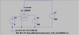
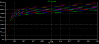
Plotting the results when sweeping multiple voltage sources
Hi. Just got around to trying this. Easy enough to setup the voltage sources.
How do I get LTSpice to plot nice plate characteristics?
I've done a lot of searching but maybe I'm using the wrong keywords.
They are not really models, just simple schematics. All you need to do in the schematic is to sweep the voltage sources on the plate and the grid for a triode. For the pentode, you add another voltage source for the screen grid, and set the voltage per the datasheets. Before you can do that, make sure you have the correct symbol for the pentode, since many SPICE models online have their pins swapped around.
Hi. Just got around to trying this. Easy enough to setup the voltage sources.
How do I get LTSpice to plot nice plate characteristics?
I've done a lot of searching but maybe I'm using the wrong keywords.
How do I get LTSpice to plot nice plate characteristics?
:: View topic - Generic "transient" tube curve and loadline file
How do I get LTSpice to plot nice plate characteristics?
A picture is worth a thousand words...
")

To plot the plate characteristic, put a current probe on the plate.
- Home
- Amplifiers
- Tubes / Valves
- Vacuum Tube SPICE Models