


Try this:
jazbo,
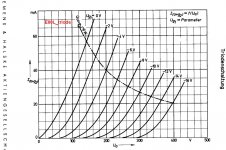
These are triode curves for E80L. If you want make AN spice model.
Excellent tube, btw
Code:
**** E80L Lorentz data***
* Created on 10/30/2013 13:10 using paint_kit.jar Version 2.4.7 Oct 2013
* [url=http://www.dmitrynizh.com/tubeparams_image.htm]Model Paint Tools: Trace Tube Parameters over Plate Curves, Interactively[/url]
* Plate Curves image file: e80l.jpg
* Data source link:
*----------------------------------------------------------------------------------
.SUBCKT E80L_T 1 2 3 ; Plate Grid Cathode
+ PARAMS: CCG=11P  CGP=3.4P CCP=7.3P RGI=2000
+ MU=22.1 KG1=636.8 KP=146.2 KVB=20.6 VCT=0.385 EX=1.49
* Vp_MAX=400 Ip_MAX=60 Vg_step=2 Vg_start=0 Vg_count=16
* Rp=4000 Vg_ac=55 P_max=8 Vg_qui=-48
* X_MIN=41 Y_MIN=21 X_SIZE=572 Y_SIZE=433 FSZ_X=1032 FSZ_Y=742 XYGrid=false
*----------------------------------------------------------------------------------
E1 7 0 VALUE={V(1,3)/KP*LOG(1+EXP(KP*(1/MU+(VCT+V(2,3))/SQRT(KVB+V(1,3)*V(1,3)))))}
RE1 7 0 1G  ; TO AVOID FLOATING NODES
G1 1 3 VALUE={(PWR(V(7),EX)+PWRS(V(7),EX))/KG1}
RCP 1 3 1G   ; TO AVOID FLOATING NODES
C1 2 3 {CCG} ; CATHODE-GRID
C2 2 1 {CGP} ; GRID=PLATE
C3 1 3 {CCP} ; CATHODE-PLATE
D3 5 3 DX ; POSITIVE GRID CURRENT
R1 2 5 {RGI} ; POSITIVE GRID CURRENT
.MODEL DX D(IS=1N RS=1 CJO=10PF TT=1N)
.ENDS
*$
Code:
.SUBCKT E80L_P  1 4 2 3  ;  25.3.2010.
+ PARAMS: MU= 23.5  EX= 1.263  KG1= 563.0  KP=149.19   KG2= 1400
+ KVB= 16.1  VCT=  0.00 RGI=1k
+ CCG=11P  CPG1=0.1P CCP=7P
RE1  7 0  1G
RE2  8 3  1G
E1   7 0  VALUE=  ; E1 BREAKS UP LONG EQUATION FOR G1.
+{V(4,3)/KP*LOG(1+EXP((1/MU+V(2,3)/V(4,3))*KP))}
G1   1 3  VALUE={(PWR(V(7),EX)+PWRS(V(7),EX))/KG1*ATAN(V(1,3)/KVB)}
G2   8 3  VALUE={(PWR(V(7),EX)+PWRS(V(7),EX))/KG2*(2.5708-ATAN(V(1,3)/KVB))}
E2   8 4  VALUE={0}
RCP  1 3  1G      ; FOR CONVERGENCE
C1   2 3  {CCG}   ; CATHODE-GRID 1
C2   1 2  {CPG1}  ; GRID 1-PLATE
C3   1 3  {CCP}   ; CATHODE-PLATE
R1   2 5  {RGI}   ; FOR GRID CURRENT
D3   5 3  DX      ; FOR GRID CURRENT
.MODEL DX D(IS=1N RS=1 CJO=10PF TT=1N)
.ENDS
jazbo,
These are triode curves for E80L. If you want make AN spice model.
Excellent tube, btw
Attachments


I don't know if I have posted in this thread before or not. I am a bass guitar player who has slowly been edging towards restoring an old tube amp or just designing one from scratch or somewhere in between. I guess I should also mention that I am an electrical engineer in my day job and while tubes were king when I was a boy (I am older than the common 9V "transistor" battery) my life's work has been spent working on solid state circuits. Except for a brief and peripheral stint with VFDs which are now being used to make low voltage audio tubes I hear. I've even done some IC design work with processes as small as 64nm and in that type of work you rely heavily on simulations with known good process models because mask sets are so expensive that it had better work 98% to spec on the first try!
So having played with tube models in LTSpice for some months now thanks to the fine information presented in this thread, I am nearing the point where I will be trying some ideas in actual hardware and the question naturally arises as to how accurate these tube models are in terms of predicting in advance the performance you can expect from a circuit. In most cases when I build an old Fender, etc, amp circuit in LTSpice using your models the results match reasonably well with what these old relics claimed to have been able to do.
Having searched this thread for answers and having found very little I am wondering if any of you who have modeled and then built up tube amps have any comments on the general accuracy of these models? Are there some things they are good at predicting and others they are poor at? Do designs require a lot of fiddling to optimize them after building what the models predicted will work? I assume this thread would have died out a long time ago if the models were completely useless! Not looking for guarantees, just comments on what your experience has been and what reasonable expectations are?
Thanks!
As long as one realizes that real devices have specification tolerances that are not captured in a SPICE model, my experience is that simulation results are reasonably accurate compared to an actual circuit. Of course, datasheets suffer from the same limitation as SPICE models, in that they represent a "typical" device that may not be a perfect representation of the tube you have in front of you.
When it comes to modeling a circuit's frequency response, particularly for frequency shaping circuits like phono preamps and tone controls, I have found that different models will give different results more often than not. These difference are generally insignificant (fractions of a dB) but are noticeable nonetheless. I usually run simulations using several models if I can, and if there is general agreement among them then I consider that good enough. Occasionally I'll find that a particular model has convergence problems in a given circuit, but having other models to choose from gets around that issue most of the time.
I should probably add that I mostly design using mainstream tubes that are still in production, so the number of models I really need in my custom library is relatively small. This practice also makes it easier to keep multiple models on hand because there are lots of 12AX7 models out there, for example.
SPICE is a great tool if you understand both its limitations as well as its capabilities.
Thanks Ray. Your experience matches what I hoped to hear but with only the ability to compare results from published schematics to the specs of the original amps so far I was not certain what to expect. I do simulations all the time at work using LTSpice some, but generally much higher priced tools (well I guess everything is much higher priced than LTSpice since it is free, eh?!) and special purpose tools too. When I was doing semiconductor designs the process variation was built into the process model so we would do designs using the nominal models and then run a "corners" analysis and tweak the design when necessary. Some things like absolute resistor values were so variable that you used circuit tricks like building circuits that depended on resistor ratios rather than resistor values to achieve the specs. And of course if a dozen transistors could do a job 7% better than one you might well consider that to be an acceptable tradeoff!
It is a far different world when you design with tubes and I do expect that the models will vary more from real world results using these models compared to the multi-million dollar model packages I had the luxury of using and depending on back then. If the results you typically get are in the right ballpark when compared to a real circuit I have the confidence I need to proceed.
Thanks again.
Glad to be of help. BTW, I too am a degreed electrical engineer from the old days, when vacuum tube circuits were still being taught in the electronics curriculum. I sure wish that tools like SPICE had been available back then! But in retrospect, I think I'm better off having learned circuit design the hard way, since I now have an appreciation for what the tool is doing "under the hood" instead of just blindly accepting whatever output the tool creates. I still start most designs with old fashioned load line analysis before ever getting into simulation. But I can get to the finish line much quicker now than in the old days.
I don't think LTspice has "difficulties" modeling transformers. LTspice actually makes it relatively easy to include parasitic elements (resistance and capacitance) in the inductor model. As is the case with other device models, the accuracy of the model depends on how close the model parameters are to real-world devices.
There are a lot of good tutorials on the Internet for how to model transformers; here is just one:
Transformer Model in LTSpice – Step by Step Guide
If you are looking for models of output transformers, Robert McLean produced a library that can serve as a good starting point. Here is his post containing the models:
SPICE Transformer Model Spreadsheet
And here is where he posted some transformer symbols that can be used with his models:
SPICE Transformer Model Spreadsheet
This should get you started.
6T9 LTSpice tube model and curves?
I have used google to look for a 6T9 LTSpice model, or barring that, curves without luck. Anyone have either?
The 6T9 is a compactron having a triode said to be a 6AV6, and a pentode identical to a 6AQ5A with a lower plate dissipation of 12 Watts. Can I use their models? or their curves? to approximate models for the triode and pentode sections of the 6T9. Assuming the curves, how do I do that?
I've found both Norman Koren's matlab tools and Teodoro Marinucci's Excel spreadsheet both of which generate LTSpice model files, but never used either before. Koren's script seems to generate a partial model to which you must hand add other parts.
Thanks for any suggestions.
rus
Yes, they should be good enough.The 6T9 is a compactron having a triode said to be a 6AV6, and a pentode identical to a 6AQ5A with a lower plate dissipation of 12 Watts. Can I use their models? or their curves?
Hello guys any idea why this spice model for the Korg 6p1 tube in Ltspice
does not work for me?
MODEL:
.SUBCKT NU6P1_l 1 2 3 ; P G C (Triode)
X1 1 2 3 TRIODE MU= 18.10 EX= 4.080 KG1=4270851.9 KP=451.94 KVB= 4.2 VCT= 0.00 RGI=330k CCG=9.1P CGP=2.5P CCP=4.3P
* http://www.nutube.us/downloads/Nutube_Datasheet_31.pdf 13-May-2017
.ENDS
does not work for me?
MODEL:
.SUBCKT NU6P1_l 1 2 3 ; P G C (Triode)
X1 1 2 3 TRIODE MU= 18.10 EX= 4.080 KG1=4270851.9 KP=451.94 KVB= 4.2 VCT= 0.00 RGI=330k CCG=9.1P CGP=2.5P CCP=4.3P
* http://www.nutube.us/downloads/Nutube_Datasheet_31.pdf 13-May-2017
.ENDS
You need to include the generic Koren triode model in your asc.
Code:
.SUBCKT TRIODE 1 2 3
E1 7 0 VALUE=
+{V(1,3)/KP*LOG(1+EXP(KP*(1/MU+V(2,3)/SQRT(KVB+V(1,3)*V(1,3)))))}
RE1 7 0 1G
G1 1 3 VALUE={(PWR(V(7),EX)+PWRS(V(7),EX))/KG1}
RCP 1 3 1G ; TO AVOID FLOATING NODES IN MU-FOLLOWER
C1 2 3 {CCG} ; CATHODE-GRID
C2 2 1 {CGP} ; GRID=PLATE
C3 1 3 {CCP} ; CATHODE-PLATE
D3 5 3 DX ; FOR GRID CURRENT
R1 2 5 {RGI} ; FOR GRID CURRENT
.MODEL DX D(IS=1N RS=1 CJO=10PF TT=1N)
.ENDS- Home
- Amplifiers
- Tubes / Valves
- Vacuum Tube SPICE Models