I have standard directives for the simulations and I copied them for simulations, yes cordell-models.txt is not necessary.
20kHz is for the same reasons, you can easy change it to any frequency you want.
30Hz sim is not bad too.
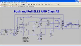
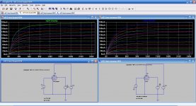
My setup would be something like below
Attachments
I tied to simulate with the Ayumi model but this is not workin
I changed the ^ into ** but no luck
I made a model according to Koren models and this seems to work
Ayumi's model works fine in LTSpice... while the EL12 Koren model you posted seems to deviate from the datasheet quite a bit.

An externally hosted image should be here but it was not working when we last tested it.
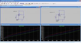
I'm sorry but it is still quite a bit off from the datasheet (particularly the upper traces), for comparison Koren's model on the left and Ayumi's model on the right:
An externally hosted image should be here but it was not working when we last tested it.
I think that this is also the case with different manufactures of tubes
A Philips wil be different than a RCA
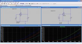
I dit found out somthing else when you look at the G2 they react different
while the Norman models react liniar the Ayumi is not.
A Philips wil be different than a RCA
I dit found out somthing else when you look at the G2 they react different
while the Norman models react liniar the Ayumi is not.
Attachments
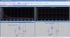
Sorry to sound like a broken record, but the screen current is poorly modeled using the Koren method. It could be improved, please refer to Dr. Gurskii's article in AA (just a bit better) or Dr. Reefman's improved methodology (great improvement), which requires the uTracer to really take advantage of it.
Sorry to sound like a broken record, but the screen current is poorly modeled using the Koren method. It could be improved, please refer to Dr. Gurskii's article in AA (just a bit better) or Dr. Reefman's improved methodology (great improvement), which requires the uTracer to really take advantage of it.
Do you know if anyone has developed a library of models for some of the common pentodes using the Reefman method? I've been using the Ayumi models because, as you note, the Koren method does not model screen current well, but I'm always on the lookout for something better.
I believe Kevin posted it earlier... if not, yes, Dr. Reefman has kindly provided some models using his improved Koren models here.
Thanks! I'll give these a try.
Jazbo8,
by this method, EF80_pentode and EF_triode have identical models.
In practice, I have not encountered such a pentode.
****************************************************
.SUBCKT EF80 1 2 3 4 ; A G2 G1 C;
* ExtractModel V .997
* Model created: 07-Dec-13
X1 1 2 3 4 PenthodeDE MU= 54.7 EX=1.202 kG1= 136.4 KP= 340.3 kVB = 4670.0 kG2= 584.2
+ Ookg1mOokG2=.56E-02 Aokg1=.23E-05 alkg1palskg2=.56E-02 be= .054 als= 3.09 RGI=2000
+ CCG1=7.5P CCG2=5.4P CPG1 = 0.007p CG1G2 = 2.6p CCP=0.012P ;
.ENDS
****************************************************
.SUBCKT EF80_triode 1 2 3; A G C;
* ExtractModel V .997
* Model created: 07-Dec-13
X1 1 2 3 TriodeK MU= 54.7 EX=1.202 KG1= 136.4 KP= 340.3 KVB= 4670. RGI=2000
+ CCG=7.5P CGP=2.6P CCP=0.0P ;
.ENDS
You are right, they do look odd, but I have no experience with this particular tube. The triode curve seems to deviate quite a bit from an example I found on the net. May be someone with EF80 can verify the results.Jazbo8,
by this method, EF80_pentode and EF_triode have identical models.
In practice, I have not encountered such a pentode.
An externally hosted image should be here but it was not working when we last tested it.
Is there any reason why the triode models would fail to work in inverted triode circuits? The generic TRIODENH model works fine, but my specific tube models fail miserably.
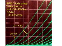
EF50 Pentode SPICE Model
Please try this one, it's not quite perfect, but should get you started...
Please try this one, it's not quite perfect, but should get you started...
Code:
*
* Generic pentode model: EF50_AN
* Copyright 2003--2008 by Ayumi Nakabayashi, All rights reserved.
* Version 3.10, Generated on Tue Jul 15 13:48:26 2014
*               Plate
*               | Screen Grid
*               | |  Control Grid
*               | |  |  Cathode
*               | |  |  |
.SUBCKT EF50_AN A G2 G1 K
BGG   GG   0 V=V(G1,K)+0.075140135
BM1   M1   0 V=(0.016755255*(URAMP(V(G2,K))+1e-10))^-1.7905817
BM2   M2   0 V=(0.45584646*(URAMP(V(GG)+URAMP(V(G2,K))/32.476589)))^3.2905817
BP    P    0 V=0.0062465593*(URAMP(V(GG)+URAMP(V(G2,K))/71.244579))^1.5
BIK   IK   0 V=U(V(GG))*V(P)+(1-U(V(GG)))*0.008577125*V(M1)*V(M2)
BIG   IG   0 V=0.0031232796*URAMP(V(G1,K))^1.5*(URAMP(V(G1,K))/(URAMP(V(A,K))+URAMP(V(G1,K)))*1.2+0.4)
BIK2  IK2  0 V=V(IK,IG)*(1-0.4*(EXP(-URAMP(V(A,K))/URAMP(V(G2,K))*15)-EXP(-15)))
BIG2T IG2T 0 V=V(IK2)*(0.62975016*(1-URAMP(V(A,K))/(URAMP(V(A,K))+10))^1.5+0.37024984)
BIK3  IK3  0 V=V(IK2)*(URAMP(V(A,K))+11000)/(URAMP(V(G2,K))+11000)
BIK4  IK4  0 V=V(IK3)-URAMP(V(IK3)-(0.0032552566*(URAMP(V(A,K))+URAMP(URAMP(V(G2,K))-URAMP(V(A,K))))^1.5))
BIP   IP   0 V=URAMP(V(IK4,IG2T)-URAMP(V(IK4,IG2T)-(0.0032552566*URAMP(V(A,K))^1.5)))
BIAK  A    K I=V(IP)+1e-10*V(A,K)
BIG2  G2   K I=URAMP(V(IK4,IP))
BIGK  G1   K I=V(IG)
* CAPS
CGA   G1  A  0.003p
CGK   G1  K  6p
C12   G1  G2 4p
CAK   A   K  5.3p
.ENDS- Home
- Amplifiers
- Tubes / Valves
- Vacuum Tube SPICE Models