Kevin,
I have been struggling with this issue for sometime, while some may not agree, but I think the culprit lies in the Koren pentode model itself, which is used in both the alternate GUI (in uTracer) and Dmitry's Paint_kip. You can improve the results with Jack's custom Excel Solver routine or Robert's multi-parameter pentode model (see his post above), but I found it is easier to use Ayumi's methodology, while not flawless (especially around the knees), it can get very good matches between the models and the datasheets. I will be making a translated version of Ayumi's article on SPICE model building available once I get my PC back, hopefully soon... or you can read the original article with Google Translate, and take a look at the equivalent circuit used for the model.
I have been struggling with this issue for sometime, while some may not agree, but I think the culprit lies in the Koren pentode model itself, which is used in both the alternate GUI (in uTracer) and Dmitry's Paint_kip. You can improve the results with Jack's custom Excel Solver routine or Robert's multi-parameter pentode model (see his post above), but I found it is easier to use Ayumi's methodology, while not flawless (especially around the knees), it can get very good matches between the models and the datasheets. I will be making a translated version of Ayumi's article on SPICE model building available once I get my PC back, hopefully soon... or you can read the original article with Google Translate, and take a look at the equivalent circuit used for the model.
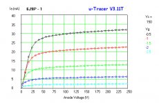
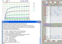
I'm a little puzzled with the quality of pentode models in spice. I used the uTracer to curve trace eight 6ж9п today and selected one that seemed to match the published curves reasonably well and generated a spice model from it using the alternate gui.
Testing in LTSpice confirmed that it did not match the measured curves closely at all. Extensive tweaking over the course of several hours got me something that looks plausible, but I don't trust it.
I subsequently used the trace from one of the tubes to generate a model using paint_kip, and was able to get a good match in the tool, but when I tested it in LTSpice again the results were not great, although much better than the untweaked model I generated using the uTracer.
Is it that these models just don't do a good job with high transconductance pentodes or as I now suspect with pentodes in general?
I did a quick sloppy trace using paint_kip and generated a model, I then added this model to my LTSpice tube library and tested it, as you can see they do not match at all. (See attachments)
Kevin,
I'm not familiar with 6Z9P, but E180F. They are very similar.
First look ..... MU=84.8 is impossible. Create a model based on MU~55 or so.
Your curves with uTracer are correct based on the datasheet.
If you atach your uTracer curves for 6Z9P only, I will try to help.
I think I broke my uTracer. Probably just a matter of replacing the output switching transistors.
The pentode models work very well in ultra-linear mode.
Credit for the Excel model should go to Pierre Teouzelet who described it in AudioXpress a few years ago. If anyone wants a copy of the spreadsheet pm and send an email address.
In the meanwhile, the pentode models will tell you whether the circuit is going to be stable. It's probably more useful to have an optimization model for the load line from which you can derive some approximation of THD% and power.
Kevin,
I'm not familiar with 6Z9P, but E180F. They are very similar.
First look ..... MU=84.8 is impossible. Create a model based on MU~55 or so.
Your curves with uTracer are correct based on the datasheet.
If you atach your uTracer curves for 6Z9P only, I will try to help.
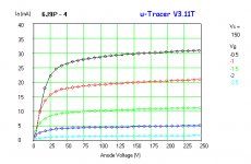
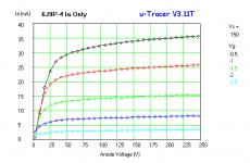
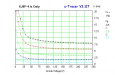
Much appreciated, here I have attached the traces of the 4 tubes that come closest to the data sheet parameters.
Edit: Interestingly enough I retraced 6j9p-4 and once again was not able to get a good fit with a mu under 80, testing in LTSpice revealed the same issue as shown in my earlier post. Changing the just mu in the model to 55 in LTSpice resulted in a good match. KG2 apparently has an effect on screen current which I am currently exploring.
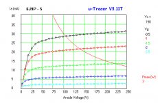
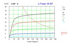
Sanity check anyone: After some tweaking the following model seems to match both expected plate currents and screen currents quite well for a screen voltage of 150V:
**** 6J9P4 ******************************************
* Created on 11/24/2013 20:06 using paint_kit.jar 2.6 by Kevin Kennedy
* www.dmitrynizh.com/tubeparams_image.htm
* Plate Curves image file: 6J9P4.gif
* Data source link:
* Model parameters MU and KG2 tweaked to match model to
* measured device params
*----------------------------------------------------------------------------------
.SUBCKT 6J9P4 1 4 2 3 ; P S G K
+ PARAMS: CCG=7.8P CGP=0.02P CCP=2.7P RGI=2000
+ MU=55 KG1=387 KP=692 KVB=12 EX=1.71 KG2=750
* Vp_MAX=250 Ip_MAX=40 Vg_step=0.5 Vg_start=-0.5 Vg_count=5
*----------------------------------------------------------------------------------
RE1 7 0 1MEG ; DUMMY SO NODE 7 HAS 2 CONNECTIONS
E1 7 0 VALUE= ; E1 BREAKS UP LONG EQUATION FOR G1.
+{V(4,3)/KP*LOG(1+EXP((1/MU+V(2,3)/V(4,3))*KP))}
G1 1 3 VALUE={(PWR(V(7),EX)+PWRS(V(7),EX))/KG1*ATAN(V(1,3)/KVB)}
G2 4 3 VALUE={(EXP(EX*(LOG((V(4,3)/MU)+V(2,3)))))/KG2}
RCP 1 3 1G ; FOR CONVERGENCE
C1 2 3 {CCG} ; CATHODE-GRID 1
C2 1 2 {CGP} ; GRID 1-PLATE
C3 1 3 {CCP} ; CATHODE-PLATE
R1 2 5 {RGI} ; FOR GRID CURRENT
D3 5 3 DX ; FOR GRID CURRENT
.MODEL DX D(IS=1N RS=1 CJO=10PF TT=1N)
.ENDS
Attachments
I think I broke my uTracer. Probably just a matter of replacing the output switching transistors.
The pentode models work very well in ultra-linear mode.
Credit for the Excel model should go to Pierre Teouzelet who described it in AudioXpress a few years ago. If anyone wants a copy of the spreadsheet pm and send an email address.
In the meanwhile, the pentode models will tell you whether the circuit is going to be stable. It's probably more useful to have an optimization model for the load line from which you can derive some approximation of THD% and power.
I recently popped the transistors in the grid bias circuit, due to an inadvertent short to the case which is at circuit ground. I ended up replacing the BC556A with MPSW56 which are more rugged, have a BVceo of -80V compared to the -65V of the '556 with a measured value collector to emitter of -74V.. They will support an amp of collector current and dissipate a watt, might be enough to survive a momentary short. For now I have added a series 470 resistor, but will replace with a 100mA fuse as I want to be able to buck the grid bias with batteries or a floating supply for curving tubes with both negative and positive values of grid bias. (The resistor is a problem when grid current starts to flow.)
I'm using high transconductance pentodes in voltage amplifier circuits and would like to have a model that provides a somewhat accurate representation of gain. Large variations in transconductance (+/-20% or more) are part and parcel of these types so I take the gain with a grain of salt, but when a model generated directly from the curves is not even close..
Kevin,
this is mine, done quickly and could be finalized.
Pay attention to the pinout P K G2 G1, due to a large IG2.
For me it is:
SUCKT 6J9P 1 2 3 4 P K G2 G1
Also, look capacitance values.
This is complete model:
**** 6J9P_4 ******************************************
* Created on 11/25/2013 00:58 using paint_kit.jar 2.6
* Model Paint Tools: Trace Tube Parameters over Plate Curves, Interactively
* Plate Curves image file: 6j9p_4.jpg
* Data source link:
*----------------------------------------------------------------------------------
.SUBCKT 6J9P**** 6J9P*************************************
* Created on 11/25/2013 00:35 using paint_kit.jar 2.6
* Model by E74GD
* Model Paint Tools: Trace Tube Parameters over Plate Curves, Interactively
* Plate Curves image file: 6j9p_4.jpg
* Data source link:
*----------------------------------------------------------------------------------
.SUBCKT 6J9P 1 4 2 3 ; P K G2 G1
+ PARAMS: CCG=8.5P CGP=0.03P CCP=3P RGI=2000
+ MU=55.9 KG1=280.9 KP=369.1 KVB=23.1 EX=1.49 KG2=1147.5
* Vp_MAX=480 Ip_MAX=40 Vg_step=0.5 Vg_start=-0.5 Vg_count=5
* Rp=1600 Vg_ac=23.5 P_max=7.5 Vg_qui=-23.4 Vp_qui=240 UL=0.469 EG2=139.2
* X_MIN=73 Y_MIN=50 X_SIZE=365 Y_SIZE=256 FSZ_X=1032 FSZ_Y=742 XYGrid=false
* showLoadLine=n showIp=y isDHT=n isPP=n isAsymPP=n isUL=n showDissipLimit=n
* showIg1=y gridLevel2=n isInputSnapped=n
* XYProjections=n harmonicPlot=y harmonics=y
*----------------------------------------------------------------------------------
RE1 7 0 1MEG ; DUMMY SO NODE 7 HAS 2 CONNECTIONS
E1 7 0 VALUE= ; E1 BREAKS UP LONG EQUATION FOR G1.
+{V(4,3)/KP*LOG(1+EXP((1/MU+V(2,3)/V(4,3))*KP))}
G1 1 3 VALUE={(PWR(V(7),EX)+PWRS(V(7),EX))/KG1*ATAN(V(1,3)/KVB)}
G2 4 3 VALUE={(EXP(EX*(LOG((V(4,3)/MU)+V(2,3)))))/KG2}
RCP 1 3 1G ; FOR CONVERGENCE
C1 2 3 {CCG} ; CATHODE-GRID 1
C2 1 2 {CGP} ; GRID 1-PLATE
C3 1 3 {CCP} ; CATHODE-PLATE
R1 2 5 {RGI} ; FOR GRID CURRENT
D3 5 3 DX ; FOR GRID CURRENT
.MODEL DX D(IS=1N RS=1 CJO=10PF TT=1N)
.ENDS
*$ 1 2 3 4 ; P G K G2
+ PARAMS: CCG=8.5P CGP=0.03P CCP=3P RGI=2000
+ MU=55.9 KG1=280.9 KP=369.1 KVB=23.1 EX=1.49 KG2=1147.5
* Vp_MAX=480 Ip_MAX=40 Vg_step=0.5 Vg_start=-0.5 Vg_count=5
* Rp=1600 Vg_ac=23.5 P_max=7.5 Vg_qui=-23.4 Vp_qui=240 UL=0.469 EG2=139.2
* X_MIN=73 Y_MIN=50 X_SIZE=365 Y_SIZE=256 FSZ_X=1032 FSZ_Y=742 XYGrid=false
* showLoadLine=n showIp=y isDHT=n isPP=n isAsymPP=n isUL=n showDissipLimit=n
* showIg1=y gridLevel2=n isInputSnapped=n
* XYProjections=n harmonicPlot=y harmonics=y
*----------------------------------------------------------------------------------
RE1 7 0 1MEG ; DUMMY SO NODE 7 HAS 2 CONNECTIONS
E1 7 0 VALUE= ; E1 BREAKS UP LONG EQUATION FOR G1.
+{V(4,3)/KP*LOG(1+EXP((1/MU+V(2,3)/V(4,3))*KP))}
G1 1 3 VALUE={(PWR(V(7),EX)+PWRS(V(7),EX))/KG1*ATAN(V(1,3)/KVB)}
G2 4 3 VALUE={(EXP(EX*(LOG((V(4,3)/MU)+V(2,3)))))/KG2}
RCP 1 3 1G ; FOR CONVERGENCE
C1 2 3 {CCG} ; CATHODE-GRID 1
C2 1 2 {CGP} ; GRID 1-PLATE
C3 1 3 {CCP} ; CATHODE-PLATE
R1 2 5 {RGI} ; FOR GRID CURRENT
D3 5 3 DX ; FOR GRID CURRENT
.MODEL DX D(IS=1N RS=1 CJO=10PF TT=1N)
.ENDS
Attachments
Sorry for wrong paste, here is again
**** 6J9P_4 ******************************************
* Created on 11/25/2013 00:58 using paint_kit.jar 2.6
* Model Paint Tools: Trace Tube Parameters over Plate Curves, Interactively
* Plate Curves image file: 6j9p_4.jpg
* Data source link:
*----------------------------------------------------------------------------------
.SUBCKT 6J9P 1 4 2 3 ; P K G2 G1
+ PARAMS: CCG=8.5P CGP=0.03P CCP=3P RGI=2000
+ MU=55.9 KG1=280.9 KP=369.1 KVB=23.1 EX=1.49 KG2=1147.5
* Vp_MAX=480 Ip_MAX=40 Vg_step=0.5 Vg_start=-0.5 Vg_count=5
* Rp=1600 Vg_ac=23.5 P_max=7.5 Vg_qui=-23.4 Vp_qui=240 UL=0.469 EG2=139.2
* X_MIN=73 Y_MIN=50 X_SIZE=365 Y_SIZE=256 FSZ_X=1032 FSZ_Y=742 XYGrid=false
* showLoadLine=n showIp=y isDHT=n isPP=n isAsymPP=n isUL=n showDissipLimit=n
* showIg1=y gridLevel2=n isInputSnapped=n
* XYProjections=n harmonicPlot=y harmonics=y
*----------------------------------------------------------------------------------
RE1 7 0 1MEG ; DUMMY SO NODE 7 HAS 2 CONNECTIONS
E1 7 0 VALUE= ; E1 BREAKS UP LONG EQUATION FOR G1.
+{V(4,3)/KP*LOG(1+EXP((1/MU+V(2,3)/V(4,3))*KP))}
G1 1 3 VALUE={(PWR(V(7),EX)+PWRS(V(7),EX))/KG1*ATAN(V(1,3)/KVB)}
G2 4 3 VALUE={(EXP(EX*(LOG((V(4,3)/MU)+V(2,3)))))/KG2}
RCP 1 3 1G ; FOR CONVERGENCE
C1 2 3 {CCG} ; CATHODE-GRID 1
C2 1 2 {CGP} ; GRID 1-PLATE
C3 1 3 {CCP} ; CATHODE-PLATE
R1 2 5 {RGI} ; FOR GRID CURRENT
D3 5 3 DX ; FOR GRID CURRENT
.MODEL DX D(IS=1N RS=1 CJO=10PF TT=1N)
.ENDS
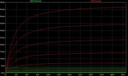
I needed to make some minor adjustments to KG2 because the screen grid current was lower than it should have been.
Interestingly enough the differences between my model and yours in LTspice were small with the exception of the screen grid current which based on the attached measurements is too low in both models. (Changing KG2 to 400 provides a reasonable approximation.)
Interestingly enough the differences between my model and yours in LTspice were small with the exception of the screen grid current which based on the attached measurements is too low in both models. (Changing KG2 to 400 provides a reasonable approximation.)
Attachments
I recently popped the transistors in the grid bias circuit, due to an inadvertent short to the case which is at circuit ground.
Upon examination, I had done the same and fried R9 -- replaced them this afternoon and it works fine.
I needed to make some minor adjustments to KG2 because the screen grid current was lower than it should have been.
Interestingly enough the differences between my model and yours in LTspice were small with the exception of the screen grid current which based on the attached measurements is too low in both models. (Changing KG2 to 400 provides a reasonable approximation.)
Right!
Today I can see better than after midnight
")
Best diying.
Here is a model for the C3g, have a box of these in the basement but never got around to play with them......
http://www.diyaudio.com/forums/tubes-valves/184331-c3g-simulation-model.html#post2491557
http://www.diyaudio.com/forums/tubes-valves/184331-c3g-simulation-model.html#post2491557
Help wanted...
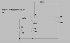
Dunno whats wrong tonight, I am getting strange simulation results no matter what I do. The curren tfrom V1 is always 1A, and nothing I do will ever make it change...is there something I need to adjust using these models? circuit as in attached picture, here is the netlist:
XU1 anode gate N001 6sn7
V1 anode 0 250
V2 gate 0 -10
R1 N001 0 100
.op
.include lib\tubes\6sn7v2.inc
.backanno
.end
..... and here is the model (include file from above):
.subckt 6sn7 P G K
Bp P K I=(0.02003791851m)*uramp(V(P,K)*ln(1.0+(-0.07740549711)+exp((4.618036737)+(4.618036737)*((20.85288965)+(-110.4389272m)*V(G,K))*V(G,K)/sqrt((28.13407639)^2+(V(P,K)-(7.118597372))^2)))/(4.618036737))^(1.380047579)
Cgp G P 4.0pF
Cgk G K 2.6pF
Cpk P K 0.7pF
.ends 6sn7
Any help much appreciated!!
Attachments
Code:
.subckt 6sn7 P G K
Bp P K I=(0.02003791851m)*uramp(V(P,K)*ln(1.0+(-0.07740549711)+exp((4.618036737)+(4.618036737)*((2 0.85288965)+(-110.4389272m)*V(G,K))*V(G,K)/sqrt((28.13407639)**2+(V(P,K)-(7.118597372))**2)))/(4.618036737))**(1.380047579)
Cgp G P 4.0pF
Cgk G K 2.6pF
Cpk P K 0.7pF
.ends 6sn7Found a space in the model were there shouldn't have been one.
Here's the corrected model:
.subckt 6sn7 P G K
Bp P K I=
+ (0.02003791851m)*uramp(V(P,K)*ln(1.0+(-0.07740549711)+exp((4.618036737)+
+ (4.618036737)*((20.85288965)+(-110.4389272m)*V(G,K))*V(G,K)/sqrt((28.13407639)**2+
+ (V(P,K)-(7.118597372))**2)))/(4.618036737))**(1.380047579)
Cgp G P 4.0pF
Cgk G K 2.6pF
Cpk P K 0.7pF
.ends 6sn7
Looks like you may be trying to sim the curves for your 6SN7 model. If so here's the file I did LTSpice using your model.
Attachments
I am looking for LTSpice models for 6H30 and 1626... Found some here, but they do not work with my LTSpice generic TRIODE model obtained from Duncan's Amp Pages.
I am new to LTSpice, so it is not clear at all how I should proceed to get this working.
Thank you for any tips you may have!
I am new to LTSpice, so it is not clear at all how I should proceed to get this working.
Thank you for any tips you may have!
many thanks cogsncogs!! Will try later today... In fact I was so desperate I tried another schematic that simulated fine in the past, and it still did - couldnt see the forest for the trees anymore, so many *** and ^^^ .....
again, many thanks!
@kevinkr: tried that , no difference. I think it is due to what cogsncogs pointed out. I should have known as I used Ayumi's models before, but I did not remember..... thanks anyway!
again, many thanks!
@kevinkr: tried that , no difference. I think it is due to what cogsncogs pointed out. I should have known as I used Ayumi's models before, but I did not remember..... thanks anyway!
Boys
I know , up to some level , how to use LT Spice ..... but I'm ignorant in making models ;
is anyone able ( and kind ) enough to make LT Spice model for this tube ?
TIA
Here you go...
Code:
*
* Generic triode model: SRS511_T
* Copyright 2003--2008 by Ayumi Nakabayashi, All rights reserved.
* Version 3.10, Generated on Sat Nov 30 19:13:05 2013
*                Plate
*                | Grid
*                | | Cathode
*                | | |
.SUBCKT SRS511_T A G K
BGG   GG   0 V=V(G,K)+0.57531149
BM1   M1   0 V=(0.024087858*(URAMP(V(A,K))+1e-10))**-0.96103099
BM2   M2   0 V=(0.60950066*(URAMP(V(GG)+URAMP(V(A,K))/16.21146)+1e-10))**2.461031
BP    P    0 V=0.0091192653*(URAMP(V(GG)+URAMP(V(A,K))/26.597937)+1e-10)**1.5
BIK   IK   0 V=U(V(GG))*V(P)+(1-U(V(GG)))*0.0059448485*V(M1)*V(M2)
BIG   IG   0 V=0.0045596326*URAMP(V(G,K))**1.5*(URAMP(V(G,K))/(URAMP(V(A,K))+URAMP(V(G,K)))*1.2+0.4)
BIAK  A    K I=URAMP(V(IK,IG)-URAMP(V(IK,IG)-(0.0050787208*URAMP(V(A,K))**1.5)))+1e-10*V(A,K)
BIGK  G    K I=V(IG)
* CAPS
CGA   G    A 0.24p
CGK   G    K 23p
CAK   A    K 13p
.ENDS- Home
- Amplifiers
- Tubes / Valves
- Vacuum Tube SPICE Models