I see. Like 6L6 supressor is internally tied to the cathode, but cathode is seperate from the heater. In the 813 for example, the filament typically has a 10v 5a 60hz sine wave flowing through it, would you still connect grid 3 to it?The suppressor grid is usually not modeled as it is typically tied to the cathode.
You can also make your own schematic symbol for the filament/cathode if that's what you want to see, it does not matter to the model.
Now when creating a schematic symbol, should I use the pin-out in the data sheet?
I tried that, and spice tells me that the pins are numbered wrong. But near as I can tell, Spice just numbers the pins in the order that you create them. Not as they are on the data sheet. If the Model (.inc file) is drawn from the data sheet, it should be looking for the pins on the symbol to be numbered according to the data sheet in order to work properly. Or am I over thinking this?
Since there very few models that contain the suppressor grid, so you must make your own model if you do NOT want to connect it to the cathode. As for schematic symbol, you can decide the pin order when it is being created, whether it follows the actual pin number of the tube in the datasheet is not important.
12E1 SPICE Models
Try these, they may work a bit better, even though not quite perfect...
Triode-Connected:
Pentode:
Try these, they may work a bit better, even though not quite perfect...
Triode-Connected:
Code:
*
* Generic triode model: 12E1_T_AN
* Copyright 2003--2008 by Ayumi Nakabayashi, All rights reserved.
* Version 3.10, Generated on Thu Nov 08 09:47:20 2018
*                 Anode
*                 | Grid
*                 | | Cathode
*                 | | |
.SUBCKT 12E1_T_AN A G K
BGG   GG   0 V=V(G,K)+1
BM1   M1   0 V=(0.19256622*(URAMP(V(A,K))+1e-10))**-1.8479145
BM2   M2   0 V=(0.44804012*(URAMP(V(GG)+URAMP(V(A,K))/2.8663381)+1e-10))**3.3479145
BP    P    0 V=0.0031089763*(URAMP(V(GG)+URAMP(V(A,K))/6.3975033)+1e-10)**1.5
BIK   IK   0 V=U(V(GG))*V(P)+(1-U(V(GG)))*0.0045711042*V(M1)*V(M2)
BIG   IG   0 V=0.0015544881*URAMP(V(G,K))**1.5*(URAMP(V(G,K))/(URAMP(V(A,K))+URAMP(V(G,K)))*1.2+0.4)
BIAK  A    K I=URAMP(V(IK,IG)-URAMP(V(IK,IG)-(0.0023112229*URAMP(V(A,K))**1.5)))+1e-10*V(A,K)
BIGK  G    K I=V(IG)
* CAPS
CGA   G    A 0.85p
CGK   G    K 23p
CAK   A    K 8p
.ENDS
Pentode:
Code:
*
* Generic pentode model: 12E1_AN
* Copyright 2003--2008 by Ayumi Nakabayashi, All rights reserved.
* Version 3.10, Generated on Thu Nov 08 09:47:38 2018
*               Anode
*               | Screen Grid
*               | |  Control Grid
*               | |  |  Cathode
*               | |  |  |
.SUBCKT 12E1_AN A G2 G1 K
BGG   GG   0 V=V(G1,K)+1
BM1   M1   0 V=(0.19256622*(URAMP(V(G2,K))+1e-10))**-1.8479145
BM2   M2   0 V=(0.44804012*(URAMP(V(GG)+URAMP(V(G2,K))/2.8663381)))**3.3479145
BP    P    0 V=0.0031089763*(URAMP(V(GG)+URAMP(V(G2,K))/6.3975033))**1.5
BIK   IK   0 V=U(V(GG))*V(P)+(1-U(V(GG)))*0.0045711042*V(M1)*V(M2)
BIG   IG   0 V=0.0015544881*URAMP(V(G1,K))**1.5*(URAMP(V(G1,K))/(URAMP(V(A,K))+URAMP(V(G1,K)))*1.2+0.4)
BIK2  IK2  0 V=V(IK,IG)*(1-0.4*(EXP(-URAMP(V(A,K))/URAMP(V(G2,K))*15)-EXP(-15)))
BIG2T IG2T 0 V=V(IK2)*(1.015196218*(1-URAMP(V(A,K))/(URAMP(V(A,K))+10))**1.5+-0.015196218)
BIK3  IK3  0 V=V(IK2)*(URAMP(V(A,K))+1537.5)/(URAMP(V(G2,K))+1537.5)
BIK4  IK4  0 V=V(IK3)-URAMP(V(IK3)-(0.0023112229*(URAMP(V(A,K))+URAMP(URAMP(V(G2,K))-URAMP(V(A,K))))**1.5))
BIP   IP   0 V=URAMP(V(IK4,IG2T)-URAMP(V(IK4,IG2T)-(0.0023112229*URAMP(V(A,K))**1.5)))
BIAK  A    K I=V(IP)+1e-10*V(A,K)
BIG2  G2   K I=URAMP(V(IK4,IP))
BIGK  G1   K I=V(IG)
* CAPS
CGA   G1  A  0.85p
CGK   G1  K  13.8p
C12   G1  G2 9.2p
CAK   A   K  8p
.ENDSI tested S11E12_P model quickly. There is no G2 current. No standing current and nothing when tube is driven full.
Your asy pin out does not match with the model, or even it does but doesn't work. So I send you here Pentode3.asy that has correct pin out and works.
No still no G2, as it's missing in the model, so I'll see why it's missed out.
===
The G2 is modeled only when param "kink" is checked in paint tool so now it's working.
Code:
**** S11E12_P ******************************************
* Created on 11/08/2018 17:44 using paint_kip.jar
* [url=http://www.dmitrynizh.com/tubeparams_image.htm]Model Paint Tools: Trace Tube Parameters over Plate Curves, Interactively[/url]
* Plate Curves image file: s11e12-p.png
* Data source link: <plate curves URL>
*----------------------------------------------------------------------------------
.SUBCKT S11E12_P P G2 G K ; LTSpice tetrode.asy pinout
* .SUBCKT S11E12_P P G K G2 ; Koren Pentode Pspice pinout
+ PARAMS: MU=5.5 KG1=1235.52 KP=34.63 KVB=0 VCT=2.687 EX=1.426 KG2=1538.46 KNEE=10.54 KVC=1.635
+ KLAM=7.424E-5 KLAMG=8.311E-5   KNK=-0.044 KNG=0.006 KNPL=50 KNSL=11 KNPR=120 KNSR=29
+ CCG=19.5P CGP=1.8P CCP=16.5P RGI=2000.0
* Vp_MAX=300 Ip_MAX=350 Vg_step=4 Vg_start=0 Vg_count=13
* X_MIN=104 Y_MIN=99 X_SIZE=554 Y_SIZE=653 FSZ_X=1550 FSZ_Y=878 XYGrid=false
* Rp=1400 Vg_ac=20 P_max=28 Vg_qui=-24 Vp_qui=300
* showLoadLine=n showIp=y isDHP=n isPP=n isAsymPP=n isUL=n showDissipLimit=y
* showIg1=n isInputSnapped=y addLocalNFB=n
* XYProjections=n harmonicPlot=y dissipPlot=n
* UL=0.43 EG2=150 gridLevel2=n addKink=y isTanhKnee=n advSigmoid=n
*----------------------------------------------------------------------------------
RE1  7 0  1G    ; DUMMY SO NODE 7 HAS 2 CONNECTIONS
E1   7 0  VALUE=  ; E1 BREAKS UP LONG EQUATION FOR G1.
+{V(G2,K)/KP*LOG(1+EXP((1/MU+(VCT+V(G,K))/SQRT(KVB+V(G2,K)*V(G2,K)))*KP))}
RE2  6 0  1G    ; DUMMY SO NODE 6 HAS 2 CONNECTIONS
E2  6 0  VALUE={(PWR(V(7),EX)+PWRS(V(7),EX))} ; Kg1 times KIT current
RE21 21 0 1
E21  21 0 VALUE={V(6)/KG1*ATAN(V(P,K)/KNEE)} ; Ip with knee but no slope and no kink
RE22 22 0 1 ; E22: kink curr deviation for plate
E22  22 0 VALUE={V(21)*LIMIT(KNK-V(G,K)*KNG,0,0.3)*(-ATAN((V(P,K)-KNPL)/KNSL)+ATAN((V(P,K)-KNPR)/KNSR))}
G1   P  K  VALUE={V(21)*(1+KLAMG*V(P,K))+KLAM*V(P,K) + V(22)}
* Alexander Gurskii screen current, see audioXpress 2/2011, with slope and kink added
RE43 43 K 1G ; Dummy
E43  43 G2 VALUE={0} ; Dummy
G2   43 K  VALUE={V(6)/KG2*(KVC-ATAN(V(P,K)/KNEE))/(1+KLAMG*V(P,K))-V(22)}
RCP  P K  1G     ; FOR CONVERGENCE
C1   K G  {CCG}  ; CATHODE-GRID 1
C2   G P  {CGP}  ; GRID 1-PLATE
C3   K P  {CCP}  ; CATHODE-PLATE
R1   G 5  {RGI}  ; FOR GRID CURRENT
D3   5 K  DX     ; FOR GRID CURRENT }
.MODEL DX D(IS=1N RS=1 CJO=10PF TT=1N)
.ENDS
*$


* The following triode model is derived from pentode model, see above.
* In the triode model, all spice parameters come directly from the pentode model, except for Kg1,
* which for triode-strapped pentodes is derived from pentode's Kg1, Kg2 and Kvc as
*
*    4Kg1Kg2 / ((2Kvc-Pi)(2Kg1+PiKg2))

**** S11E12_P ******************************************
* Created on 11/08/2018 17:44 using paint_kit.jar 4.7
* [url=http://www.dmitrynizh.com/tubeparams_image.htm]Model Paint Tools: Trace Tube Parameters over Plate Curves, Interactively[/url]
* Plate Curves image file: s11e12-p.png
* Data source link: <plate curves URL>
*----------------------------------------------------------------------------------
.SUBCKT TRIODE_S11E12_P 1 2 3 ; Plate Grid Cathode
+ PARAMS: CCG=19.5P  CGP=1.8P CCP=16.5P RGI=2000
+ MU=5.5 KG1=8106.89 KP=34.63 KVB=0 VCT=2.687 EX=1.426
* Vp_MAX=300 Ip_MAX=350 Vg_step=4 Vg_start=0 Vg_count=13
* Rp=1400 Vg_ac=20 P_max=28 Vg_qui=-24 Vp_qui=300
* X_MIN=104 Y_MIN=99 X_SIZE=554 Y_SIZE=653 FSZ_X=1550 FSZ_Y=878 XYGrid=false
* showLoadLine=n showIp=y isDHT=n isPP=n isAsymPP=n showDissipLimit=y
* showIg1=n gridLevel2=n isInputSnapped=y
* XYProjections=n harmonicPlot=y dissipPlot=n
*----------------------------------------------------------------------------------
E1 7 0 VALUE={V(1,3)/KP*LOG(1+EXP(KP*(1/MU+(VCT+V(2,3))/SQRT(KVB+V(1,3)*V(1,3)))))}
RE1 7 0 1G  ; TO AVOID FLOATING NODES
G1 1 3 VALUE={(PWR(V(7),EX)+PWRS(V(7),EX))/KG1}
RCP 1 3 1G   ; TO AVOID FLOATING NODES
C1 2 3 {CCG} ; CATHODE-GRID
C2 2 1 {CGP} ; GRID=PLATE
C3 1 3 {CCP} ; CATHODE-PLATE
D3 5 3 DX ; POSITIVE GRID CURRENT
R1 2 5 {RGI} ; POSITIVE GRID CURRENT
.MODEL DX D(IS=1N RS=1 CJO=10PF TT=1N)
.ENDS
*$
Attachments
Great! Thanx for the info.Since there very few models that contain the suppressor grid, so you must make your own model if you do NOT want to connect it to the cathode. As for schematic symbol, you can decide the pin order when it is being created, whether it follows the actual pin number of the tube in the datasheet is not important.
Hello all,
Does any of you have a model for the 6AU5GT?
Thanks in advance!
Bringing this back from the dead (sorry). If I upload lots of traced curves and a data sheet (attached), might it be possible to whip up a 6AU5GT model that would be 'close enough for jazz'?
--
Attachments
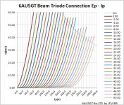
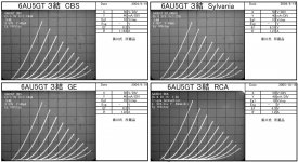
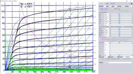
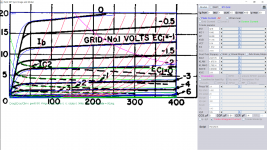
6AU5GT SPICE Models
Triode-Connected:
Pentode
Triode-Connected:
Code:
*
* Generic triode model: 6AU5GT_T_AN
* Copyright 2003--2008 by Ayumi Nakabayashi, All rights reserved.
* Version 3.10, Generated on Fri Nov 09 07:48:41 2018
*                   Anode
*                   | Grid
*                   | | Cathode
*                   | | |
.SUBCKT 6AU5GT_T_AN A G K
BGG   GG   0 V=V(G,K)+1
BM1   M1   0 V=(0.16180684*(URAMP(V(A,K))+1e-10))**-1.5041156
BM2   M2   0 V=(0.499315*(URAMP(V(GG)+URAMP(V(A,K))/3.0943376)+1e-10))**3.0041156
BP    P    0 V=0.0020691217*(URAMP(V(GG)+URAMP(V(A,K))/6.1971653)+1e-10)**1.5
BIK   IK   0 V=U(V(GG))*V(P)+(1-U(V(GG)))*0.0020776667*V(M1)*V(M2)
BIG   IG   0 V=0.0010345609*URAMP(V(G,K))**1.5*(URAMP(V(G,K))/(URAMP(V(A,K))+URAMP(V(G,K)))*1.2+0.4)
BIAK  A    K I=URAMP(V(IK,IG)-URAMP(V(IK,IG)-(0.0015550746*URAMP(V(A,K))**1.5)))+1e-10*V(A,K)
BIGK  G    K I=V(IG)
* CAPS
CGA   G    A 0.5p
CGK   G    K 11p
CAK   A    K 7p
.ENDS
Pentode
Code:
*
* Generic pentode model: 6AU5GT_AN
* Copyright 2003--2008 by Ayumi Nakabayashi, All rights reserved.
* Version 3.10, Generated on Fri Nov 09 07:48:22 2018
*                 Anode
*                 | Screen Grid
*                 | |  Control Grid
*                 | |  |  Cathode
*                 | |  |  |
.SUBCKT 6AU5GT_AN A G2 G1 K
BGG   GG   0 V=V(G1,K)+1
BM1   M1   0 V=(0.16197411*(URAMP(V(G2,K))+1e-10))**-1.503003
BM2   M2   0 V=(0.4995*(URAMP(V(GG)+URAMP(V(G2,K))/3.09)))**3.003003
BP    P    0 V=0.0020737569*(URAMP(V(GG)+URAMP(V(G2,K))/6.1861862))**1.5
BIK   IK   0 V=U(V(GG))*V(P)+(1-U(V(GG)))*0.00208*V(M1)*V(M2)
BIG   IG   0 V=0.0010368784*URAMP(V(G1,K))**1.5*(URAMP(V(G1,K))/(URAMP(V(A,K))+URAMP(V(G1,K)))*1.2+0.4)
BIK2  IK2  0 V=V(IK,IG)*(1-0.4*(EXP(-URAMP(V(A,K))/URAMP(V(G2,K))*15)-EXP(-15)))
BIG2T IG2T 0 V=V(IK2)*(0.9287*(1-URAMP(V(A,K))/(URAMP(V(A,K))+10))**1.5+0.0713)
BIK3  IK3  0 V=V(IK2)*(URAMP(V(A,K))+1160)/(URAMP(V(G2,K))+1160)
BIK4  IK4  0 V=V(IK3)-URAMP(V(IK3)-(0.0015595183*(URAMP(V(A,K))+URAMP(URAMP(V(G2,K))-URAMP(V(A,K))))**1.5))
BIP   IP   0 V=URAMP(V(IK4,IG2T)-URAMP(V(IK4,IG2T)-(0.0015595183*URAMP(V(A,K))**1.5)))
BIAK  A    K I=V(IP)+1e-10*V(A,K)
BIG2  G2   K I=URAMP(V(IK4,IP))
BIGK  G1   K I=V(IG)
* CAPS
CGA   G1  A  0.5p
CGK   G1  K  6.6p
C12   G1  G2 4.4p
CAK   A   K  7p
.ENDSI have to estimate unknown G2 current, the unknown Mu is adjusted for best fit too. In your sim connect G2 to Anode for triode operation.Hello,
I'm looking for a model for EL183 in triode?
Thx.
Code:
**** EL183_P ******************************************
* Created on 11/10/2018 00:58 using paint_kip.jar
* [url=http://www.dmitrynizh.com/tubeparams_image.htm]Model Paint Tools: Trace Tube Parameters over Plate Curves, Interactively[/url]
* Plate Curves image file: el183_p.png
* Data source link: <plate curves URL>
*----------------------------------------------------------------------------------
.SUBCKT EL183_P P G2 G K ; LTSpice tetrode.asy pinout
* .SUBCKT EL183_P P G K G2 ; Koren Pentode Pspice pinout
+ PARAMS: MU=50.23 KG1=247.68 KP=373.55 KVB=1.695 VCT=0.003125 EX=1.394 KG2=378 KNEE=18.18 KVC=1.571
+ KLAM=1.68E-7 KLAMG=4.43E-4 KNEE2=20 KNEX=30  KNK=-0.044 KNG=0.006 KNPL=50 KNSL=11 KNPR=120 KNSR=29
+ CCG=13P CGP=0.08P CCP=5.4P RGI=2000.0
* Vp_MAX=300 Ip_MAX=110 Vg_step=0.5 Vg_start=0 Vg_count=11
* X_MIN=58 Y_MIN=40 X_SIZE=1015 Y_SIZE=761 FSZ_X=1550 FSZ_Y=878 XYGrid=false
* Rp=1400 Vg_ac=20 P_max=6 Vg_qui=-2.5 Vp_qui=300
* showLoadLine=n showIp=y isDHP=n isPP=n isAsymPP=n isUL=n showDissipLimit=y
* showIg1=n isInputSnapped=y addLocalNFB=n
* XYProjections=n harmonicPlot=y dissipPlot=n
* UL=0.43 EG2=220 gridLevel2=n addKink=y isTanhKnee=y advSigmoid=n
*----------------------------------------------------------------------------------
RE1  7 0  1G    ; DUMMY SO NODE 7 HAS 2 CONNECTIONS
E1   7 0  VALUE=  ; E1 BREAKS UP LONG EQUATION FOR G1.
+{V(G2,K)/KP*LOG(1+EXP((1/MU+(VCT+V(G,K))/SQRT(KVB+V(G2,K)*V(G2,K)))*KP))}
RE2  6 0  1G    ; DUMMY SO NODE 6 HAS 2 CONNECTIONS
E2  6 0  VALUE={(PWR(V(7),EX)+PWRS(V(7),EX))} ; Kg1 times KIT current
RE21 21 0 1
E21  21 0 VALUE={V(6)/KG1*ATAN((V(P,K)+KNEX)/KNEE)*TANH(V(P,K)/KNEE2)} ; Ip with knee but no slope and no kink
RE22 22 0 1 ; E22: kink curr deviation for plate
E22  22 0 VALUE={V(21)*LIMIT(KNK-V(G,K)*KNG,0,0.3)*(-ATAN((V(P,K)-KNPL)/KNSL)+ATAN((V(P,K)-KNPR)/KNSR))}
G1   P  K  VALUE={V(21)*(1+KLAMG*V(P,K))+KLAM*V(P,K) + V(22)}
* Alexander Gurskii screen current, see audioXpress 2/2011, with slope and kink added
RE43 43 K 1G ; Dummy
E43  43 G2 VALUE={0} ; Dummy
G2   43 K  VALUE={V(6)/KG2*(KVC-ATAN((V(P,K)+KNEX)/KNEE)*TANH(V(P,K)/KNEE2))/(1+KLAMG*V(P,K))-V(22)}
RCP  P K  1G     ; FOR CONVERGENCE
C1   K G  {CCG}  ; CATHODE-GRID 1
C2   G P  {CGP}  ; GRID 1-PLATE
C3   K P  {CCP}  ; CATHODE-PLATE
R1   G 5  {RGI}  ; FOR GRID CURRENT
D3   5 K  DX     ; FOR GRID CURRENT }
.MODEL DX D(IS=1N RS=1 CJO=10PF TT=1N)
.ENDS
*$


* The following triode model is derived from pentode model, see above.
* In the triode model, all spice parameters come directly from the pentode model, except for Kg1,
* which for triode-strapped pentodes is derived from pentode's Kg1, Kg2 and Kvc as
*
*    4Kg1Kg2 / ((2Kvc-Pi)(2Kg1+PiKg2))

**** EL183_P ******************************************
* Created on 11/10/2018 00:58 using paint_kit.jar 4.7
* [url=http://www.dmitrynizh.com/tubeparams_image.htm]Model Paint Tools: Trace Tube Parameters over Plate Curves, Interactively[/url]
* Plate Curves image file: el183_p.png
* Data source link: <plate curves URL>
*----------------------------------------------------------------------------------
.SUBCKT TRIODE_EL183_P 1 2 3 ; Plate Grid Cathode
+ PARAMS: CCG=13P  CGP=0.08P CCP=5.4P RGI=2000
+ MU=50.23 KG1=556324.71 KP=373.55 KVB=1.695 VCT=0.003125 EX=1.394
* Vp_MAX=300 Ip_MAX=110 Vg_step=0.5 Vg_start=0 Vg_count=11
* Rp=1400 Vg_ac=20 P_max=6 Vg_qui=-2.5 Vp_qui=300
* X_MIN=58 Y_MIN=40 X_SIZE=1015 Y_SIZE=761 FSZ_X=1550 FSZ_Y=878 XYGrid=false
* showLoadLine=n showIp=y isDHT=n isPP=n isAsymPP=n showDissipLimit=y
* showIg1=n gridLevel2=n isInputSnapped=y
* XYProjections=n harmonicPlot=y dissipPlot=n
*----------------------------------------------------------------------------------
E1 7 0 VALUE={V(1,3)/KP*LOG(1+EXP(KP*(1/MU+(VCT+V(2,3))/SQRT(KVB+V(1,3)*V(1,3)))))}
RE1 7 0 1G  ; TO AVOID FLOATING NODES
G1 1 3 VALUE={(PWR(V(7),EX)+PWRS(V(7),EX))/KG1}
RCP 1 3 1G   ; TO AVOID FLOATING NODES
C1 2 3 {CCG} ; CATHODE-GRID
C2 2 1 {CGP} ; GRID=PLATE
C3 1 3 {CCP} ; CATHODE-PLATE
D3 5 3 DX ; POSITIVE GRID CURRENT
R1 2 5 {RGI} ; POSITIVE GRID CURRENT
.MODEL DX D(IS=1N RS=1 CJO=10PF TT=1N)
.ENDS
*$
Attachments
Last edited:
Hi,
I'm looking for LTspice model for 6EA8/6GH8.
Thanks for Yr Help.
Triode connected Pentode has nearly the same Mu as Triode section.
Code:
**** 6EA8_T ******************************************
* Created on 11/10/2018 13:47 using paint_kit.jar 3.1
* [url=http://www.dmitrynizh.com/tubeparams_image.htm]Model Paint Tools: Trace Tube Parameters over Plate Curves, Interactively[/url]
* Plate Curves image file: 6ea8_t.png
* Data source link:
*----------------------------------------------------------------------------------
.SUBCKT TRIODE_6EA8_T 1 2 3 ; Plate Grid Cathode
+ PARAMS: CCG=5P  CGP=1.7P CCP=3P RGI=2000
+ MU=40 KG1=690 KP=138 KVB=264 VCT=0.592 EX=1.512
* Vp_MAX=400 Ip_MAX=50 Vg_step=1 Vg_start=0 Vg_count=15
* Rp=4000 Vg_ac=55 P_max=2.5 Vg_qui=-48 Vp_qui=300
* X_MIN=83 Y_MIN=65 X_SIZE=957 Y_SIZE=599 FSZ_X=1550 FSZ_Y=878 XYGrid=false
* showLoadLine=n showIp=y isDHT=n isPP=n isAsymPP=n showDissipLimit=y
* showIg1=n gridLevel2=n isInputSnapped=n
* XYProjections=n harmonicPlot=n dissipPlot=n
*----------------------------------------------------------------------------------
E1 7 0 VALUE={V(1,3)/KP*LOG(1+EXP(KP*(1/MU+(VCT+V(2,3))/SQRT(KVB+V(1,3)*V(1,3)))))}
RE1 7 0 1G  ; TO AVOID FLOATING NODES
G1 1 3 VALUE={(PWR(V(7),EX)+PWRS(V(7),EX))/KG1}
RCP 1 3 1G   ; TO AVOID FLOATING NODES
C1 2 3 {CCG} ; CATHODE-GRID
C2 2 1 {CGP} ; GRID=PLATE
C3 1 3 {CCP} ; CATHODE-PLATE
D3 5 3 DX ; POSITIVE GRID CURRENT
R1 2 5 {RGI} ; POSITIVE GRID CURRENT
.MODEL DX D(IS=1N RS=1 CJO=10PF TT=1N)
.ENDS
*$
Code:
**** 6EA8_P ******************************************
* Created on 11/10/2018 13:20 using paint_kip.jar
* [url=http://www.dmitrynizh.com/tubeparams_image.htm]Model Paint Tools: Trace Tube Parameters over Plate Curves, Interactively[/url]
* Plate Curves image file: 6ea8_p.png
* Data source link: <plate curves URL>
*----------------------------------------------------------------------------------
.SUBCKT 6EA8_P P G2 G K ; LTSpice tetrode.asy pinout
* .SUBCKT 6EA8_P P G K G2 ; Koren Pentode Pspice pinout
+ PARAMS: MU=42.8 KG1=1045 KP=84.09 KVB=11.16 VCT=0.14 EX=1.512 KG2=2604 KNEE=0.03938 KVC=3.11
+ KLAM=1.67E-6 KLAMG=2.76E-4 KNEE2=20 KNEX=30  KNK=-0.044 KNG=0.006 KNPL=50 KNSL=11 KNPR=120 KNSR=29
+ CCG=5P CGP=0.01P CCP=3.4P RGI=2000.0
* Vp_MAX=400 Ip_MAX=20 Vg_step=1 Vg_start=0 Vg_count=15
* X_MIN=55 Y_MIN=50 X_SIZE=961 Y_SIZE=492 FSZ_X=1550 FSZ_Y=878 XYGrid=false
* Rp=1400 Vg_ac=20 P_max=3.1 Vg_qui=-7 Vp_qui=300
* showLoadLine=n showIp=y isDHP=n isPP=n isAsymPP=n isUL=n showDissipLimit=y
* showIg1=n isInputSnapped=y addLocalNFB=n
* XYProjections=n harmonicPlot=y dissipPlot=n
* UL=0.43 EG2=125 gridLevel2=n addKink=y isTanhKnee=y advSigmoid=n
*----------------------------------------------------------------------------------
RE1  7 0  1G    ; DUMMY SO NODE 7 HAS 2 CONNECTIONS
E1   7 0  VALUE=  ; E1 BREAKS UP LONG EQUATION FOR G1.
+{V(G2,K)/KP*LOG(1+EXP((1/MU+(VCT+V(G,K))/SQRT(KVB+V(G2,K)*V(G2,K)))*KP))}
RE2  6 0  1G    ; DUMMY SO NODE 6 HAS 2 CONNECTIONS
E2  6 0  VALUE={(PWR(V(7),EX)+PWRS(V(7),EX))} ; Kg1 times KIT current
RE21 21 0 1
E21  21 0 VALUE={V(6)/KG1*ATAN((V(P,K)+KNEX)/KNEE)*TANH(V(P,K)/KNEE2)} ; Ip with knee but no slope and no kink
RE22 22 0 1 ; E22: kink curr deviation for plate
E22  22 0 VALUE={V(21)*LIMIT(KNK-V(G,K)*KNG,0,0.3)*(-ATAN((V(P,K)-KNPL)/KNSL)+ATAN((V(P,K)-KNPR)/KNSR))}
G1   P  K  VALUE={V(21)*(1+KLAMG*V(P,K))+KLAM*V(P,K) + V(22)}
* Alexander Gurskii screen current, see audioXpress 2/2011, with slope and kink added
RE43 43 K 1G ; Dummy
E43  43 G2 VALUE={0} ; Dummy
G2   43 K  VALUE={V(6)/KG2*(KVC-ATAN((V(P,K)+KNEX)/KNEE)*TANH(V(P,K)/KNEE2))/(1+KLAMG*V(P,K))-V(22)}
RCP  P K  1G     ; FOR CONVERGENCE
C1   K G  {CCG}  ; CATHODE-GRID 1
C2   G P  {CGP}  ; GRID 1-PLATE
C3   K P  {CCP}  ; CATHODE-PLATE
R1   G 5  {RGI}  ; FOR GRID CURRENT
D3   5 K  DX     ; FOR GRID CURRENT }
.MODEL DX D(IS=1N RS=1 CJO=10PF TT=1N)
.ENDS
*$


* The following triode model is derived from pentode model, see above.
* In the triode model, all spice parameters come directly from the pentode model, except for Kg1,
* which for triode-strapped pentodes is derived from pentode's Kg1, Kg2 and Kvc as
*
*    4Kg1Kg2 / ((2Kvc-Pi)(2Kg1+PiKg2))

**** 6EA8_P ******************************************
* Created on 11/10/2018 13:20 using paint_kit.jar 4.7
* [url=http://www.dmitrynizh.com/tubeparams_image.htm]Model Paint Tools: Trace Tube Parameters over Plate Curves, Interactively[/url]
* Plate Curves image file: 6ea8_p.png
* Data source link: <plate curves URL>
*----------------------------------------------------------------------------------
.SUBCKT TRIODE_6EA8_P 1 2 3 ; Plate Grid Cathode
+ PARAMS: CCG=5P  CGP=0.01P CCP=3.4P RGI=2000
+ MU=42.8 KG1=344.33 KP=84.09 KVB=11.16 VCT=0.14 EX=1.512
* Vp_MAX=400 Ip_MAX=20 Vg_step=1 Vg_start=0 Vg_count=15
* Rp=1400 Vg_ac=20 P_max=3.1 Vg_qui=-7 Vp_qui=300
* X_MIN=55 Y_MIN=50 X_SIZE=961 Y_SIZE=492 FSZ_X=1550 FSZ_Y=878 XYGrid=false
* showLoadLine=n showIp=y isDHT=n isPP=n isAsymPP=n showDissipLimit=y
* showIg1=n gridLevel2=n isInputSnapped=y
* XYProjections=n harmonicPlot=y dissipPlot=n
*----------------------------------------------------------------------------------
E1 7 0 VALUE={V(1,3)/KP*LOG(1+EXP(KP*(1/MU+(VCT+V(2,3))/SQRT(KVB+V(1,3)*V(1,3)))))}
RE1 7 0 1G  ; TO AVOID FLOATING NODES
G1 1 3 VALUE={(PWR(V(7),EX)+PWRS(V(7),EX))/KG1}
RCP 1 3 1G   ; TO AVOID FLOATING NODES
C1 2 3 {CCG} ; CATHODE-GRID
C2 2 1 {CGP} ; GRID=PLATE
C3 1 3 {CCP} ; CATHODE-PLATE
D3 5 3 DX ; POSITIVE GRID CURRENT
R1 2 5 {RGI} ; POSITIVE GRID CURRENT
.MODEL DX D(IS=1N RS=1 CJO=10PF TT=1N)
.ENDS
*$
There is an actual 46 SE schematic using 6ea8 with voltage data you can verify with the model.
Attachments
Code:
**** 2E22AG2G3 ******************************************
* Created on 11/11/2018 01:21 using paint_kit.jar 3.1
* [url=http://www.dmitrynizh.com/tubeparams_image.htm]Model Paint Tools: Trace Tube Parameters over Plate Curves, Interactively[/url]
* Plate Curves image file: 2E22AG2G3.png
* Data source link:
*----------------------------------------------------------------------------------
.SUBCKT TRIODE_2E22AG2G3 1 2 3 ; Plate Grid Cathode
+ PARAMS: CCG=13P  CGP=0.2P CCP=8P RGI=2000
+ MU=8.939 KG1=4159.32 KP=49.18 KVB=37.5 VCT=0 EX=1.705
* Vp_MAX=550 Ip_MAX=140 Vg_step=5 Vg_start=0 Vg_count=11
* Rp=4000 Vg_ac=55 P_max=30 Vg_qui=-48 Vp_qui=300
* X_MIN=26 Y_MIN=166 X_SIZE=1026 Y_SIZE=537 FSZ_X=1550 FSZ_Y=878 XYGrid=false
* showLoadLine=n showIp=y isDHT=n isPP=n isAsymPP=n showDissipLimit=y
* showIg1=n gridLevel2=n isInputSnapped=n
* XYProjections=n harmonicPlot=n dissipPlot=n
*----------------------------------------------------------------------------------
E1 7 0 VALUE={V(1,3)/KP*LOG(1+EXP(KP*(1/MU+(VCT+V(2,3))/SQRT(KVB+V(1,3)*V(1,3)))))}
RE1 7 0 1G  ; TO AVOID FLOATING NODES
G1 1 3 VALUE={(PWR(V(7),EX)+PWRS(V(7),EX))/KG1}
RCP 1 3 1G   ; TO AVOID FLOATING NODES
C1 2 3 {CCG} ; CATHODE-GRID
C2 2 1 {CGP} ; GRID=PLATE
C3 1 3 {CCP} ; CATHODE-PLATE
D3 5 3 DX ; POSITIVE GRID CURRENT
R1 2 5 {RGI} ; POSITIVE GRID CURRENT
.MODEL DX D(IS=1N RS=1 CJO=10PF TT=1N)
.ENDS
*$
Attachments
- Home
- Amplifiers
- Tubes / Valves
- Vacuum Tube SPICE Models