You are welcome, the 7859 triode model could probably use some improvement, let me know if you need it.
I gather from the dates on the two nuvistor files that you created them just before posting them, Using the Ayumi Nakabayashi template or system.
Did you fill in the model data from the RCA datasheets or were these models already in the Nakabayashi collection? How can I tell if the model is working correctly? I presume that one would run some curves in spice and compare them to the data sheet curves. (not sure how to set that up).
I also presume that the heaters are not in the models, but that the models represent the functioning of the tube at nominal 6.3V heater voltages.
Yes, I used the Ayumi template to generate the SPICE models based on the RCA datasheets. The Ayumi SPICE models do not model the heaters. Once you have the models set up in LTSpice, you can plot out and compare the models' characteristics with the datasheets by overlay the curves using a graphic program such as Inkscape.
Alternative 7859 Triode Model
Code:
* SPIEC Model Generated with Curve Captor Copyright (C) 2001-2005 Andrei Frolov
* 7895 model based on RCA datasheet by jazbo8 on April 18, 2016
.SUBCKT 7895_AF P G K
Bp  P K  I=(0.002792114283m)*uramp(V(P,K)*ln(1.0+(-0.007921377953)+exp((0.029581058)+(0.029581058)*((3947.799129)+(-275542.0296m)*V(G,K))*V(G,K)/sqrt((46.11727264)**2+(V(P,K)-(14.43981838))**2)))/(0.029581058))**(1.146266009)
CGA   G    P 0.9p
CGK   G    K 4.2p
CAK   P    K 1.7p
D3 5 K DX     ;
R1 G 5 2000  ;
.MODEL DX D(IS=1N RS=1 CJO=10PF TT=1N)
.ENDSSorry for so many questions.
I notice that the 7587_AN model starts out with Generic Pentode model. Does the fact that the 7587 is a tetrode affect the accuracy of the model? You can see that I don't yet understand the inner workings of the numbers in the model. With the exception of the interelectrode capacitances, which I can see from the RCA data sheet and the numbers in the spice model (for the 7895) are the average of the min and max values on the datasheet. I just noticed that the part number for the 7895 model has a typo (it read 7859_AN). Is it your opinion that the second 7895 model is more accurate than the _AN version?
Thanks for your patience with my questions. The better I understand what is going on in the models, the better.
It does, especially where the tetrode kink is located, other than using Dr. Reefman's ExtractModel, I don't know of any other model building tool that can do a good job with tetrodes, but it means that you must purchase an uTracer curve tracer.Does the fact that the 7587 is a tetrode affect the accuracy of the model?
Good catch, I will fix that. Yes, the second one, the Frolov model is much more accurate IMO.I just noticed that the part number for the 7895 model has a typo (it read 7859_AN). Is it your opinion that the second 7895 model is more accurate than the _AN version?
You are welcome, the 7859 triode model could probably use some improvement, let me know if you need it.
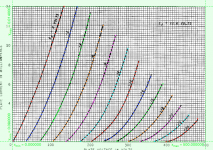
I compared the Ayumi 7895 model with the one I use, optimizing in Excel, fixing mu at 65 for the latter. Both simulated numbers run in Multisim match well, but both deviate in the same way from the data sheet!
I ran my numbers through the safe operating area -- under 1 watt.
My other model for the 6CW4 nuvistor works very well.
12J5 model (negative bias only)
Code:
*
* Generic triode model: 12J5
* Copyright 2003--2008 by Ayumi Nakabayashi, All rights reserved.
* Version 3.10, Generated on Wed Apr 20 07:18:20 2016
*            Plate
*            | Grid
*            | | Cathode
*            | | |
.SUBCKT 12J5 A G K
BGG   GG   0 V=V(G,K)+0.7884484
BM1   M1   0 V=(0.013715092*(URAMP(V(A,K))+1e-10))**-0.47044075
BM2   M2   0 V=(0.761251*(URAMP(V(GG)+URAMP(V(A,K))/17.407757)+1e-10))**1.9704407
BP    P    0 V=0.00089453094*(URAMP(V(GG)+URAMP(V(A,K))/22.867302)+1e-10)**1.5
BIK   IK   0 V=U(V(GG))*V(P)+(1-U(V(GG)))*0.00051842727*V(M1)*V(M2)
BIG   IG   0 V=0.00044726547*URAMP(V(G,K))**1.5*(URAMP(V(G,K))/(URAMP(V(A,K))+URAMP(V(G,K)))*1.2+0.4)
BIAK  A    K I=URAMP(V(IK,IG)-URAMP(V(IK,IG)-(0.00050657988*URAMP(V(A,K))**1.5)))+1e-10*V(A,K)
BIGK  G    K I=V(IG)
* CAPS
CGA   G    A 3.4p
CGK   G    K 3.4p
CAK   A    K 3.6p
.ENDS
Attachments
Last edited:
12J5 model (including positive bias)
Code:
*
* Generic triode model: 12J5_positive
* Copyright 2003--2008 by Ayumi Nakabayashi, All rights reserved.
* Version 3.10, Generated on Wed Apr 20 07:36:06 2016
*                     Plate
*                     | Grid
*                     | | Cathode
*                     | | |
.SUBCKT 12J5_positive A G K
BGG   GG   0 V=V(G,K)+0.81657826
BM1   M1   0 V=(0.012045594*(URAMP(V(A,K))+1e-10))**-0.40203768
BM2   M2   0 V=(0.78862791*(URAMP(V(GG)+URAMP(V(A,K))/17.547669)+1e-10))**1.9020377
BP    P    0 V=0.00081633583*(URAMP(V(GG)+URAMP(V(A,K))/22.250885)+1e-10)**1.5
BIK   IK   0 V=U(V(GG))*V(P)+(1-U(V(GG)))*0.00048081041*V(M1)*V(M2)
BIG   IG   0 V=0.00040816791*URAMP(V(G,K))**1.5*(URAMP(V(G,K))/(URAMP(V(A,K))+URAMP(V(G,K)))*1.2+0.4)
BIAK  A    K I=URAMP(V(IK,IG)-URAMP(V(IK,IG)-(0.00046381335*URAMP(V(A,K))**1.5)))+1e-10*V(A,K)
BIGK  G    K I=V(IG)
* CAPS
CGA   G    A 3.4p
CGK   G    K 3.4p
CAK   A    K 3.6p
.ENDS
Attachments
I tried the 7587 tetrode model in my circuit, but I was unable to make it behave in a way that seems to make sense. The circuit is a push-pull line output amplifier using an output transformer. I was attempting to use a current mirror in place of the separate 300 Ohm cathode resistors to force the DC bias currents to be identical in both tubes. No matter how I adjust the values, the tetrode will not do more than 4 mA bias, and the screen grid voltage is dropping to as low as 23 V due to excessive current flow from B+ through the 120K screen grid isolation resistor. The Ampex schematic shows 52V at the screen grids. I tried it on the factory circuit, which shows 1.5V at the junction of each cathode and its 300 Ohm resistor (5mA), but the model doesn't respond like the Ampex schematic says.
Is it possible to tweak the Spice model to help it behave more like the real thing? or am I doomed to trying all the ideas out on the bench?
Thanks for all your help.
Is it possible to tweak the Spice model to help it behave more like the real thing? or am I doomed to trying all the ideas out on the bench?
Thanks for all your help.
Last edited:
While the 7587 model is not perfectly accurate, it should still give you useful results in the simulations. Please take a look at the bias conditions below, if the Ampex figures are correct, then Ip=5.5mA, Ig2=1.7mA, so Ik = 7.2mA, but that would make Vk = 2.16V, which can't be right... Working it another way, Ig2 = (275-52)/120k = 1.858mA, since the Ig2 is proportional to Ip, that means Ip has to be greater than 5.5mA, thus making Vk even higher than before, which does not make sense either...

BTW, what is the specification for the output transformer? How are you modeling it?
BTW, what is the specification for the output transformer? How are you modeling it?
Does anybody have LT Spice model for 1J29B ?
http://tec.org.ru/_bd/18/1809_129-.pdf
http://tec.org.ru/_bd/18/1809_129-.pdf
I'm wondering if a spice model for PC97 or EC97 HF triode is possible.
Can plate curves be inferred from the curves on page 5 of the PC97 pdf?
http://www.soemtron.org/downloads/disposals/pc97.pdf
EC97 data is basically identical:
https://frank.pocnet.net/sheets/030/e/EC97.pdf
--
Can plate curves be inferred from the curves on page 5 of the PC97 pdf?
http://www.soemtron.org/downloads/disposals/pc97.pdf
EC97 data is basically identical:
https://frank.pocnet.net/sheets/030/e/EC97.pdf
--
uTracer derived Parameter adjustment due to self heating?
Hi,
I am not sure if this topic has been covered.
I am using the uTracer for parameter extraction, and generally am delighted with the accuracy of the performance of the models in sim vs bench tests.
However a few tubes show a higher actual Ia than simulated (and uTracer measured) quiescent current on the bench, that on observation seem to be due to self heating effects of the tube as a result of plate dissipation? The uTracer being a pulsed measurement would not heat the plate in the same way.
Low power tubes like the 6SN7 do not show these effects, but power pentodes generally do, whilst miniature dual triode such as 6922 also show self heating.
The difference in operating point can be quite marked (10-25% for the 6922) when simulated in a simple common cathode circuit.
I am using the Koren model for the 6922, so by adjusting the parameter KG1 (which I understand is essentially the parameter k from the original Langmuir-Childs law and represents some aspect of the diode physical structure (plate spacing)) I can get good agreement between dc conditions around the operating point of interest and subsequent good agreement in a cascode test circuit I built. Parameter KG1 is the most significant parameter influencing Ia at normal bias conditions.
Does this make sense to make an adjustment like this, or am I being too simplistic, and is there a better way?
If there is any interest I can present the measure vs simulated results.
Thank you!Active.
But is there a method to make triode passive-like source? Or it is impossible anyway?
Probably not, since the tubes have wide tolerances to begin with, ±20% is fine for simulation purpose.Does this make sense to make an adjustment like this, or am I being too simplistic, and is there a better way?
Not sure why you want to do such thing, but if you find a way to do it, please let us know.But is there a method to make triode passive-like source? Or it is impossible anyway?
uTracer derived Parameter adjustment due to self heating?
Agreed, but it remains interesting from a modelling perspective.
I had another think about this & I'm not convinced that just changing one parameter is a good idea. Looking at the Koren formula on a spreadsheet & making the adjustment changes the curve too much I can't see that it can be correct.
It may help if I understood what the physical phenomena is that will cause Ia to increase as the tube warms up on application of Va? I suppose it is purely a mechanical phenomena?
If the anode heats & expands, I presume the anode-cathode spacing may increase, this means mu will increase, which seems to decrease Ia, and as the spacing increases the simple diode model also says Ia will decrease too.
Both heading in the wrong direction, Ia increases! So there must be another phenomena, any ideas?
Probably not, since the tubes have wide tolerances to begin with, ±20% is fine for simulation purpose.
Agreed, but it remains interesting from a modelling perspective.
I had another think about this & I'm not convinced that just changing one parameter is a good idea. Looking at the Koren formula on a spreadsheet & making the adjustment changes the curve too much I can't see that it can be correct.
It may help if I understood what the physical phenomena is that will cause Ia to increase as the tube warms up on application of Va? I suppose it is purely a mechanical phenomena?
If the anode heats & expands, I presume the anode-cathode spacing may increase, this means mu will increase, which seems to decrease Ia, and as the spacing increases the simple diode model also says Ia will decrease too.
Both heading in the wrong direction, Ia increases!
So there must be another phenomena, any ideas?I have done a few more measurements using the KG1 "adjustment" described above ^^^
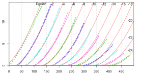
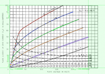
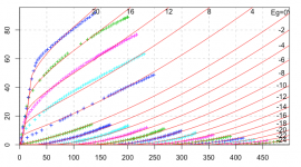
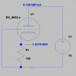
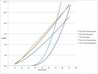
I used a simple common cathode (CC) circuit shown, and made static measurements of Ia as the supply V1 varies. The results are shown in the graph.
The dark blue line "CC with uTracer param" is the simulated curve using the Koren triode parameters generated by the uTracer; the red "CC with adj param" is the simulated curve with KG1 changed as described; the green "CC measured" curve is the bench test actual measured curve. You can see the closer correlation between the measured and adjusted parameter curves.
The other 2 curves show Ia vs Va for the triode with uTracer and adjusted parameters and shows the marked differences when KG1 is changed.
I have conducted some small and large (1V pk-pk) signal simulation vs tests and again get greater agreement with the simulation using the adjusted parameter than with the original uTracer parameters.
Finally I tried to "preheat" the tube by applying dc quiescent conditions to the tube then quickly moving it to the uTracer to test! I tried to keep it "toasty" with a cloth, but to no avail. Although there was a change it was not significant.
Attachments
- Home
- Amplifiers
- Tubes / Valves
- Vacuum Tube SPICE Models