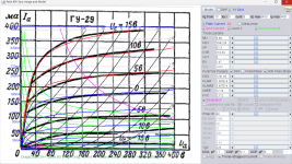
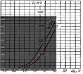
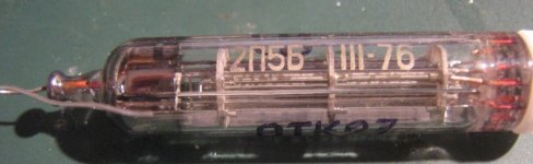
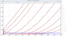
Here is GU-29 (ГУ-29) model:
Code:
**** GU_29 ******************************************
* Created on 10/24/2022 16:08 using paint_kip.jar
* www.dmitrynizh.com/tubeparams_image.htm
* Plate Curves image file: GU-29.png
* Data source link: <plate curves URL>
*----------------------------------------------------------------------------------
.SUBCKT GU_29 P G2 G K ; LTSpice tetrode.asy pinout
* .SUBCKT GU_29 P G K G2 ; Koren Pentode Pspice pinout
+ PARAMS: MU=9.88 KG1=1842.28 KP=52.3 KVB=110.59 VCT=0 EX=1.47 KG2=1781.85 KNEE=17.76 KVC=2.112
+ KLAM=1.562E-9 KLAMG=3.657E-4  KD=0.01004 KC=0.1544 KR1=172.5 KR2=11.6 KVBG=0.2775 KB1=0.3886 KB2=1.9 KB3=1.88 KB4=5.664 KVBGI=25.91 KNK=1.221E-5 KNG=0.00929 KNPL=8.898E-4 KNSL=0.02145 KNPR=51.53 KNSR=48.44
+ CCG=17P CGP=0.1P CCP=9P VGOFF=-0.6 IGA=0.001 IGB=0.3 IGC=8 IGEX=2
* Vp_MAX=400 Ip_MAX=400 Vg_step=5 Vg_start=15 Vg_count=9
* X_MIN=93 Y_MIN=94 X_SIZE=672 Y_SIZE=540 FSZ_X=1296 FSZ_Y=736 XYGrid=true
* Rp=1400 Vg_ac=20 P_max=40 Vg_qui=-5 Vp_qui=300
* showLoadLine=n showIp=y isDHP=n isPP=n isAsymPP=n isUL=n showDissipLimit=y
* showIg1=y isInputSnapped=y addLocalNFB=n
* XYProjections=n harmonicPlot=y dissipPlot=n
* UL=0.43 EG2=225 gridLevel2=y addKink=y isTanhKnee=n advSigmoid=y
*----------------------------------------------------------------------------------
RE1  7 0  1G    ; DUMMY SO NODE 7 HAS 2 CONNECTIONS
E1   7 0  VALUE=  ; E1 BREAKS UP LONG EQUATION FOR G1.
+{V(G2,K)/KP*LOG(1+EXP((1/MU+(VCT+V(G,K))/SQRT(KVB+V(G2,K)*V(G2,K)))*KP))}
RE2  6 0  1G    ; DUMMY SO NODE 6 HAS 2 CONNECTIONS
E2  6 0  VALUE={(PWR(V(7),EX)+PWRS(V(7),EX))} ; Kg1 times KIT current
E4   8 0  VALUE={V(P,K)/KNEE/(KVBGI+V(6)*KVBG)}
E5  81 0  VALUE={PWR(V(8),KB1)}
E6  82 0  VALUE={PWR(V(8),KB2)}
E7  83 0  VALUE={PWR(V(8),KB3)}
E8   9 0  VALUE={PWR(1-EXP(-V(81)*(KC+KR1*V(82))/(KD+KR2*V(83))),KB4)*1.5708}
RE4  8 0  1
RE5 81 0  1
RE6 82 0  1
RE7 83 0  1
RE8  9 0  1
RE21 21 0 1
E21  21 0 VALUE={V(6)/KG1*V(9)} ; Ip with knee but no slope and no kink
RE22 22 0 1 ; E22: kink curr deviation for plate
E22  22 0 VALUE={V(21)*LIMIT(KNK-V(G,K)*KNG,0,0.3)*(-ATAN((V(P,K)-KNPL)/KNSL)+ATAN((V(P,K)-KNPR)/KNSR))}
G1   P K  VALUE={V(21)*(1+KLAMG*V(P,K))+KLAM*V(P,K) + V(22)}
G2   G2 K  VALUE={V(6)/KG2*(KVC-V(9))/(1+KLAMG*V(P,K)) - V(22)}
RCP  P K  1G     ; FOR CONVERGENCE
C1   K G  {CCG}  ; CATHODE-GRID 1
C2   G P  {CGP}  ; GRID 1-PLATE
C3   K P  {CCP}  ; CATHODE-PLATE
RE23 G 0 1G
GG G K VALUE={(IGA+IGB/(IGC+V(P,K)))*(MU/KG1)*
+(PWR(V(G,K)-VGOFF,IGEX)+PWRS(V(G,K)-VGOFF,IGEX))}
.ENDS
*$
Attachments
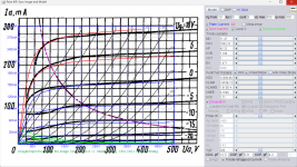
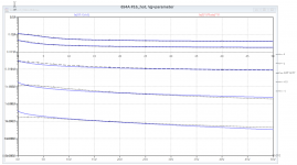
Here is GU-19 (ГУ-19) model:
Code:
**** GU_19 ******************************************
* Created on 10/24/2022 21:52 using paint_kip.jar
* www.dmitrynizh.com/tubeparams_image.htm
* Plate Curves image file: GU-19.png
* Data source link: <plate curves URL>
*------------------------------------------------------------good1----------------------
.SUBCKT GU_19 P G2 G K ; LTSpice tetrode.asy pinout
* .SUBCKT GU_19 P G K G2 ; Koren Pentode Pspice pinout
+ PARAMS: MU=11.47 KG1=1582.22 KP=45.32 KVB=7.188 VCT=1 EX=1.471 KG2=12399.98 KNEE=0.1698 KVC=1.71
+ KLAM=1.953E-11 KLAMG=1.813E-4 KNEE2=39.46 KNEX=1137.6  KNK=0.03105 KNG=2.397E-4 KNPL=0.8299 KNSL=0.6589 KNPR=125.33 KNSR=40.45
+ CCG=12.5P CGP=0.8P CCP=4.2P VGOFF=-0.6 IGA=0.001 IGB=0.3 IGC=8 IGEX=2
* Vp_MAX=500 Ip_MAX=300 Vg_step=5 Vg_start=10 Vg_count=9
* X_MIN=78 Y_MIN=89 X_SIZE=672 Y_SIZE=509 FSZ_X=1296 FSZ_Y=736 XYGrid=true
* Rp=1400 Vg_ac=20 P_max=21 Vg_qui=-10 Vp_qui=300
* showLoadLine=n showIp=y isDHP=n isPP=n isAsymPP=n isUL=n showDissipLimit=y
* showIg1=y isInputSnapped=y addLocalNFB=n
* XYProjections=n harmonicPlot=y dissipPlot=n
* UL=0.43 EG2=200 gridLevel2=y addKink=y isTanhKnee=y advSigmoid=n
*----------------------------------------------------------------------------------
RE1  7 0  1G    ; DUMMY SO NODE 7 HAS 2 CONNECTIONS
E1   7 0  VALUE=  ; E1 BREAKS UP LONG EQUATION FOR G1.
+{V(G2,K)/KP*LOG(1+EXP((1/MU+(VCT+V(G,K))/SQRT(KVB+V(G2,K)*V(G2,K)))*KP))}
RE2  6 0  1G    ; DUMMY SO NODE 6 HAS 2 CONNECTIONS
E2  6 0  VALUE={(PWR(V(7),EX)+PWRS(V(7),EX))} ; Kg1 times KIT current
RE21 21 0 1
E21  21 0 VALUE={V(6)/KG1*ATAN((V(P,K)+KNEX)/KNEE)*TANH(V(P,K)/KNEE2)} ; Ip with knee but no slope and no kink
RE22 22 0 1 ; E22: kink curr deviation for plate
E22  22 0 VALUE={V(21)*LIMIT(KNK-V(G,K)*KNG,0,0.3)*(-ATAN((V(P,K)-KNPL)/KNSL)+ATAN((V(P,K)-KNPR)/KNSR))}
G1   P  K  VALUE={V(21)*(1+KLAMG*V(P,K))+KLAM*V(P,K) + V(22)}
* Alexander Gurskii screen current, see audioXpress 2/2011, with slope and kink added
RE43 43 K 1G ; Dummy
E43  43 G2 VALUE={0} ; Dummy
G2   43 K  VALUE={V(6)/KG2*(KVC-ATAN((V(P,K)+KNEX)/KNEE)*TANH(V(P,K)/KNEE2))/(1+KLAMG*V(P,K))-V(22)}
RCP  P K  1G     ; FOR CONVERGENCE
C1   K G  {CCG}  ; CATHODE-GRID 1
C2   G P  {CGP}  ; GRID 1-PLATE
C3   K P  {CCP}  ; CATHODE-PLATE
RE23 G 0 1G
GG G K VALUE={(IGA+IGB/(IGC+V(P,K)))*(MU/KG1)*
+(PWR(V(G,K)-VGOFF,IGEX)+PWRS(V(G,K)-VGOFF,IGEX))}
.ENDS
*$
Attachments
01A
all versions pspice model
.
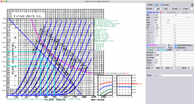
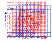
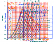
I put together all anode curves from different manufacturers of the 01-A type small DH triode
And it seems that there are very little or no difference.
I add Bartola measured chrs for 301 type (note that 2V Ug step against the 1.5V step from other, that also fits very strongly.
.
sorry for the model TXT file missing some error occurred when closing java model extractor...
But the values of the parameters are visible
0.7pF added for each electrode for additional capacitance of the socket (Norman K. note)
cheers
all versions pspice model
.
I put together all anode curves from different manufacturers of the 01-A type small DH triode
And it seems that there are very little or no difference.
I add Bartola measured chrs for 301 type (note that 2V Ug step against the 1.5V step from other, that also fits very strongly.
.
sorry for the model TXT file missing some error occurred when closing java model extractor...
But the values of the parameters are visible
0.7pF added for each electrode for additional capacitance of the socket (Norman K. note)
cheers
Attachments
Hi all
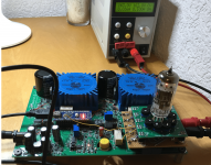
Just note that I did an important enhancement to my iTracrer, to further improve my models accuracy. Like the famous uTracer, my iTracer applies pulses to the tube of interest, and measures the plate and grid currents during this pulses.
I got recently the hint, that this method has the drawback of a cold staying anode, while in practice, the anode is hot due to the losses. It depends on the tube construction whether this has any influence to the curves. The field is wide open, from "no influence" (=very good construction) to "20% different gm" (bad construction). Also, mu, Island effect and grid current can be influenced by the late losses.
I introduced now an enhancement with reed relays, switching the tube between iTracer (during the measurement pulses) and a DC power supply for a working point with about 70% of the maximum allowed plate losses. See picture!
A first tube I measured, the 6S4A, showed a gm redirection of 4% under hot plate conditions.
BR Adrian
Attachments
Hi all
Here it is, my first i6 spice model. The i6 version is actually an i5 version, but measured with hot plate. This way, it can be easily distinguished whether the tube was measured with cold or hot anode.
all the best,
Adrian
Here it is, my first i6 spice model. The i6 version is actually an i5 version, but measured with hot plate. This way, it can be easily distinguished whether the tube was measured with cold or hot anode.
all the best,
Adrian
Code:
*6S4A LTspice model based on the generic triode model from Adrian Immler, version i6
*A version log is at the end of this file
*100h BurnIn of 7 tubes, sample selection and measurements done in March 2022
*Params fitted to the measured values by Adrian Immler, October 2022
*This model is accurate for Vg up to 4V.
*The high fit quality is presented at adrianimmler.simplesite.com
*History's best of tube describing art (plus some new ideas) is merged to this new approach.
*@ neg. Vg, Ia accuracy is similar to Koren models, and unrivaled for remote cutoff triodes
*@ small neg. Vg, the "Anlauf" current is considered.
*@ pos. Vg, Ig and Ia accuracy is on an unrivaled level (including neg. Va range!)
*This offers new simulation possibilities like grid resistor bias, backward plate modulated stages,
*Audion radio circuits, low voltage amps, guitar distortion stages or pulsed stages.
*            3R = plate version with 3 ribs (there is also one with 2 ribs, with different curves)
*            | i6 version is identical to the i5, but measurements done with HOT anode for highest accuracy
*            | |
*            | |  anode (plate)
*            | |  | grid
*            | |  | | cathode
*            | |  | | |
.subckt 6S4A.3Ri6 A G K
+ params:
*Parameters for space charge current Is (100% assigned to Ia @ Vg < 0)
+ mu   = 19.1  ;Determines the voltage gain @ constant Ia
+ rad  = 3k53  ;Differential anode resistance, set @ Iad and Vg=0V
+ Vct  = 0.55  ;Offsets the Ia-traces on the Va axis. Electrode material's contact potential
+ kp   = 100   ;Mimics the island effect
+ xs   = 1.35  ;Determines the curve of the Ia traces. Typically between 1.2 and 1.8
+ kIsr = 12m   ;Va-indepedent part of the Is reduction when gridcurrent occurs
+ kvdg  = 600  ;Va-depedent part of the Is reduction when gridcurrent occurs
*
*Parameters for assigning the space charge current to Ia and Ig @ Vg > 0
+ kB   = 0.9   ;Describes how fast Ia drops to zero when Va approaches zero.
+ radl = 380   ;Differential resistance for the Ia emission limit @ very small Va and Vg > 0
+ tsh  = 12    ;Ia transmission sharpness from 1th to 2nd Ia area. Keep between 3 and 20. Start with 20.
+ xl   = 1.1   ;Exponent for the emission limit
*
*Parameters of the grid-cathode vacuum diode
+ kg = 3k5     ;Inverse scaling factor for the Va independent part of Ig (caution - interacts with xg!)
+ Vctg = 0.38  ;Offsets the log Ig-traces on the Vg axis. Electrode material's contact potential
+ xg   = 1.2   ;Determines the curve of the Ig slope versus (positive) Vg and Va >> 0
+ VT   = 0.128 ;Log(Ig) slope @ Vg<0. VT=k/q*Tk (cathodes absolute temp, typically 1150K)
+ rTr  = 0.8   ;ratio of VT for Igr. Typically 0.8
+ kVT  = -18m  ;Va dependant koeff. of VT
+ gft1 = 0     ;reduces the steering voltage around Vg=-Vg0, for finetuning purposes
+ gft1a= 0     ;reduces the steering voltage around Vg=-Vg0. Effect decreases with 1/(1+kB*Va)
+ gft2 = 0     ;finetunes the Igr drop @ incrasing Va and around Vg=-Vg0
*
*Parameters for the caps
+ cag  = 2p4   ;From GE datasheet
+ cak  = 0p6   ;From GE datasheet
+ cgk  = 4p2   ;From GE datasheet
*
*special purpose parameters
+ os = 1       ;Overall scaling factor, if a user wishes to simulate manufacturing tolerances
+ murc = 10    ;Mu of the remote cutoff triode
+ ksrc = 10G   ;Inverse Iarc gain factor for the remote cuttoff triode
+ kprc = 1k    ;Mimics the island effect for the remote cotoff triode
+ Vbatt = 0    ;heater battery voltage for direct heated battery triodes
+ Vdrmax = 100 ;max voltage of internal Vg drop, for convergence improvements
*
*Calculated parameters
+ Iad = {100/rad} ;Ia where the anode a.c. resistance is set according to rad.
+ ks = {pow(mu/(rad*xs*Iad**(1-1/xs)),-xs)} ;Reduces the unwished xs influence to the Ia slope
+ ksnom = {pow(mu/(rad*1.5*Iad**(1-1/1.5)),-1.5)} ;Sub-equation for calculating Vg0
+ Vg0 = {Vct + (Iad*ks)**(1/xs) - (Iad*ksnom)**(2/3)} ;Reduces the xs influence to Vct.
+ kl = {pow(1/(radl*xl*Ild**(1-1/xl)),-xl)} ;Reduces the xl influence to the Ia slope @ small Va
+ Ild = {sqrt(radl)*1m} ;Current where the Il a.c. resistance is set according to radl.
*
*Space charge current model
Rak A K 100G ;avoids "floating net" errors
Bft   ft 0 V=1/(1+pow(2*abs(v(G,Ki)+Vg0),3)) ;an auxiliary voltage to finetune the triode around Vg=-Vg0
Bggi GGi 0 V=(v(Gi,Ki)+Vg0)*(1/(1+kIsr*max(0, v(G,Ki)+Vg0))) - gft1*v(ft) - gft1a*v(ft)/(1+kB*v(Ahc)) ;Effective internal grid voltage.
Bahc Ahc 0 V=uramp(v(A,Ki)) ;Anode voltage, hard cut to zero @ neg. value
Bst   St 0 V=uramp(max(v(GGi)+v(A,Ki)/(mu), v(A,Ki)/kp*ln(1+exp(kp*(1/mu+v(GGi)/(1+v(Ahc)))))));Steering volt.
Bs    Ai Ki I=os/ks*pow(v(St),xs) ;Langmuir-Childs law for the space charge current Is
*Bstrc Strc 0 V=uramp(max(v(GGi)+v(Ahc)/(murc), v(Ahc)/kprc*ln(1+exp(kprc*(1/murc+v(GGi)/(1+v(Ahc)))))));FOR REMOTE CUTOFF TUBES ONLY
*Bsrc   Ai Ki I=os/ksrc*pow(v(Strc),xs) ;FOR REMOTE CUTOFF TUBES ONLY
*
*Anode current limit @ small Va
.func smin(z,y,k) {pow(pow(z+1f, -k)+pow(y+1f, -k), -1/k)} ;Min-function with smooth trans.
.func ssmin(z,y,k) {min(min(z,y), smin(z*1.003,y*1.003,k))};smin-function which suppresses small residual differencies
Ra  A Ai 1
Bgl Gi A I=uramp(i(Ra)-ssmin(1/kl*pow(v(Ahc),xl),i(Ra),tsh)) ;Ia emission limit
*
*Grid model
Rgk G K 10G ;avoids "floating net" errors
Bvdg G Gi I=1/kvdg*pow(v(G,Gi),1.5) ;Reduces the internal effective grid voltage when Ig rises
Bcoh G Gi I=pow(uramp(v(G,Gi)-Vdrmax),2) ;A convergence help which softly limits the internal Vg voltage drop.
Rgip G Gi 1G ;avoids some warnings
.func fVT() {VT*exp(-kVT*sqrt(v(A,Ki)))}
.func Ivd(Vvd, kvd, xvd, VTvd)  {if(Vvd < 3, 1/kvd*pow(VTvd*xvd*ln(1+exp(Vvd/VTvd/xvd)),xvd), 1/kvd*pow(Vvd, xvd))} ;Vacuum diode function
Bgvd G Ki I=Ivd(v(G,Ki) + Vctg + min(0,v(A,Ki)/mu), kg/os, xg, fVT()) ;limits the internal Vg for convergence reasons
Bstn Stn 0 V=v(GGi)+min(0,v(A,Ki))/mu ;special steering voltage, sensitive to negative Anodevoltages only
Bgr Gi Ai I= ivd(v(Stn),ks/os, xs, rTr*fVT())/(1+(kB+v(ft)*gft2)*v(Ahc));Is reflection to grid when Va approaches zero
*Bgr Gi Ai I=(ivd(v(Stn),ks/os, xs, rTr*fVT())+os/ksrc*pow(v(GGi),xs))/(1+(kB+v(ft)*gft2)*v(Ahc));FOR REMOTE CUTOFF TUBES ONLY
Bs0 Ai Ki  I=uramp(ivd(v(Stn),ks/os, xs, rTr*fVT()) - os/ks*pow(v(Stn),xs))
Bbatt Ki K V=Vbatt/2 ;for battery heated triodes; Offsets the average cathode potential to the half heater battery voltage
*
*Caps
C1 A G {cag}
C2 A K {cak}
C3 G K {cgk}
.ends
*
*Version log
*i1 :Initial version
*i2 :Pin order changed to the more common order A G K (Thanks to Markus Gyger for his tip)
*i3 :bugfix of the Ivd-function: now also usable for larger Vvd
*i4: Rgi replaced by a virtual vacuum diode (better convergence). ft1 deleted (no longer needed)
;2 new prarams for Ig finetuning @ Va and Vg near zero. New overall skaling factor os for aging etc.
*i5: improved convergence performance. PosVg/NegVa area now correct. Also accurate now for remote cutoff triodes!
*i6: identical to the i5, but tubes measured with hot anode (Pa=0.7*Pmax) for highest accuracy
Attachments
Hi Adrian,Hi Pedro
For the 1j29b, I have an older one on my website.
adrianimmler.simplesite.com
But it is based on one sample only, while this tube is known for larger tolerances - so take that into account when you use my model.
BR Adrian
Thanks for the reply.
One more thing.
From what I see from the datasheets, the 1j29b (since it can deliver a considerable amount of current) can be used on the power stage, whereas the 1j24b would be suitable for the pre-amp. Do you agree with this?
Cheers,
Pedro
Hi,
I have these 2 models of 12BY7A from Ayumi Nakabayashi, which are I going to use with LTSpice. One with "_AN" suffix and another without. Last doesn't have .ENDS for some reason.
What is the difference between these 2, one triode connection and another penthode? If yes, which is which? Thanks in advance.
Code:
*
* Generic pentode model: 12BY7A
* Copyright 2003--2008 by Ayumi Nakabayashi, All rights reserved.
* Version 3.10, Generated on Fri Dec 27 09:04:07 2013
* Plate
* | Screen Grid
* | | Control Grid
* | | | Cathode
* | | | |
.SUBCKT 12BY7A P G2 G1 K
BGG GG 0 V=V(G1,K)+0.65943158
BM1 M1 0 V=(0.012147484*(URAMP(V(G2,K))+1e-10))**-0.63410138
BM2 M2 0 V=(0.70287195*(URAMP(V(GG)+URAMP(V(G2,K))/24.460049)))**2.1341014
BP P 0 V=0.0067627064*(URAMP(V(GG)+URAMP(V(G2,K))/34.80015))**1.5
BIK IK 0 V=U(V(GG))*V(P)+(1-U(V(GG)))*0.0039175034*V(M1)*V(M2)
BIG IG 0 V=0.0033813532*URAMP(V(G1,K))**1.5*(URAMP(V(G1,K))/(URAMP(V(P,K))+URAMP(V(G1,K)))*1.2+0.4)
BIK2 IK2 0 V=V(IK,IG)*(1-0.4*(EXP(-URAMP(V(P,K))/URAMP(V(G2,K))*15)-EXP(-15)))
BIG2T IG2T 0 V=V(IK2)*(0.82100762*(1-URAMP(V(P,K))/(URAMP(V(P,K))+10))**1.5+0.17899238)
BIK3 IK3 0 V=V(IK2)*(URAMP(V(P,K))+5958)/(URAMP(V(G2,K))+5958)
BIK4 IK4 0 V=V(IK3)-URAMP(V(IK3)-(0.0036749321*(URAMP(V(P,K))+URAMP(URAMP(V(G2,K))-URAMP(V(P,K))))**1.5))
BIP IP 0 V=URAMP(V(IK4,IG2T)-URAMP(V(IK4,IG2T)-(0.0036749321*URAMP(V(P,K))**1.5)))
BIAK P K I=V(IP)+1e-10*V(P,K)
BIG2 G2 K I=URAMP(V(IK4,IP))
BIGK G1 K I=V(IG)
* CAPS
CGP G1 P 0.063p
CGK G1 K 6p
C12 G1 G2 4p
CPK P K 3.5p
.ENDS

*********************************************************************

*
* Generic pentode model: 12BY7A_AN
* Copyright 2003--2008 by Ayumi Nakabayashi, All rights reserved.
* Version 3.10, Generated on Fri Dec 27 09:04:07 2013
*                 Plate
*                 | Screen Grid
*                 | |  Control Grid
*                 | |  |  Cathode
*                 | |  |  |
.SUBCKT 12BY7A_AN A G2 G1 K
BGG   GG   0 V=V(G1,K)+0.65943158
BM1   M1   0 V=(0.012147484*(URAMP(V(G2,K))+1e-10))**-0.63410138
BM2   M2   0 V=(0.70287195*(URAMP(V(GG)+URAMP(V(G2,K))/24.460049)))**2.1341014
BP    P    0 V=0.0067627064*(URAMP(V(GG)+URAMP(V(G2,K))/34.80015))**1.5
BIK   IK   0 V=U(V(GG))*V(P)+(1-U(V(GG)))*0.0039175034*V(M1)*V(M2)
BIG   IG   0 V=0.0033813532*URAMP(V(G1,K))**1.5*(URAMP(V(G1,K))/(URAMP(V(A,K))+URAMP(V(G1,K)))*1.2+0.4)
BIK2  IK2  0 V=V(IK,IG)*(1-0.4*(EXP(-URAMP(V(A,K))/URAMP(V(G2,K))*15)-EXP(-15)))
BIG2T IG2T 0 V=V(IK2)*(0.82100762*(1-URAMP(V(A,K))/(URAMP(V(A,K))+10))**1.5+0.17899238)
BIK3  IK3  0 V=V(IK2)*(URAMP(V(A,K))+5958)/(URAMP(V(G2,K))+5958)
BIK4  IK4  0 V=V(IK3)-URAMP(V(IK3)-(0.0036749321*(URAMP(V(A,K))+URAMP(URAMP(V(G2,K))-URAMP(V(A,K))))**1.5))
BIP   IP   0 V=URAMP(V(IK4,IG2T)-URAMP(V(IK4,IG2T)-(0.0036749321*URAMP(V(A,K))**1.5)))
BIAK  A    K I=V(IP)+1e-10*V(A,K)
BIG2  G2   K I=URAMP(V(IK4,IP))
BIGK  G1   K I=V(IG)
* CAPS
CGA   G1  A  0.063p
CGK   G1  K  6p
C12   G1  G2 4p
CAKThese two models have the same date and time and appear to be the same except for the last line in the second model and the second model's missing .ENDS statement. They are both pentode (actually tetrode) models.
Ayumi did produce both pentode and triode-connected models for the 12BY7A. Both are shown below.
Pentode Model:
Triode-Connected Model:
Ayumi did produce both pentode and triode-connected models for the 12BY7A. Both are shown below.
Pentode Model:
Code:
*
* Generic pentode model: 12BY7A
* Copyright 2003--2008 by Ayumi Nakabayashi, All rights reserved.
* Version 3.10, Generated on Sat Mar  8 22:41:15 2008
*              Plate
*              | Screen Grid
*              | |  Control Grid
*              | |  |  Cathode
*              | |  |  |
.SUBCKT 12BY7A A G2 G1 K
BGG   GG   0 V=V(G1,K)+-0.02185341
BM1   M1   0 V=(0.014593712*(URAMP(V(G2,K))+1e-10))**-0.7027291
BM2   M2   0 V=(0.68097344*(URAMP(V(GG)+URAMP(V(G2,K))/21.860549)))**2.2027291
BP    P    0 V=0.0061475247*(URAMP(V(GG)+URAMP(V(G2,K))/32.101912))**1.5
BIK   IK   0 V=U(V(GG))*V(P)+(1-U(V(GG)))*0.0036081888*V(M1)*V(M2)
BIG   IG   0 V=0.0030737623*URAMP(V(G1,K))**1.5*(URAMP(V(G1,K))/(URAMP(V(A,K))+URAMP(V(G1,K)))*1.2+0.4)
BIK2  IK2  0 V=V(IK,IG)*(1-0.4*(EXP(-URAMP(V(A,K))/URAMP(V(G2,K))*15)-EXP(-15)))
BIG2T IG2T 0 V=V(IK2)*(0.82512147*(1-URAMP(V(A,K))/(URAMP(V(A,K))+10))**1.5+0.17487853)
BIK3  IK3  0 V=V(IK2)*(URAMP(V(A,K))+4890)/(URAMP(V(G2,K))+4890)
BIK4  IK4  0 V=V(IK3)-URAMP(V(IK3)-(0.0033632383*(URAMP(V(A,K))+URAMP(URAMP(V(G2,K))-URAMP(V(A,K))))**1.5))
BIP   IP   0 V=URAMP(V(IK4,IG2T)-URAMP(V(IK4,IG2T)-(0.0033632383*URAMP(V(A,K))**1.5)))
BIAK  A    K I=V(IP)+1e-10*V(A,K)
BIG2  G2   K I=URAMP(V(IK4,IP))
BIGK  G1   K I=V(IG)
* CAPS
CGA   G1  A  0.063p
CGK   G1  K  6.1p
C12   G1  G2 4.1p
CAK   A   K  3.4p
.ENDS
Triode-Connected Model:
Code:
*
* Generic triode model: 12BY7AT
* Copyright 2003--2008 by Ayumi Nakabayashi, All rights reserved.
* Version 3.10, Generated on Sat Mar  8 22:41:15 2008
*               Plate
*               | Grid
*               | | Cathode
*               | | |
.SUBCKT 12BY7AT A G K
BGG   GG   0 V=V(G,K)+-0.02185341
BM1   M1   0 V=(0.014593712*(URAMP(V(A,K))+1e-10))**-0.7027291
BM2   M2   0 V=(0.68097344*(URAMP(V(GG)+URAMP(V(A,K))/21.860549)+1e-10))**2.2027291
BP    P    0 V=0.0061475247*(URAMP(V(GG)+URAMP(V(A,K))/32.101912)+1e-10)**1.5
BIK   IK   0 V=U(V(GG))*V(P)+(1-U(V(GG)))*0.0036081888*V(M1)*V(M2)
BIG   IG   0 V=0.0030737623*URAMP(V(G,K))**1.5*(URAMP(V(G,K))/(URAMP(V(A,K))+URAMP(V(G,K)))*1.2+0.4)
BIAK  A    K I=URAMP(V(IK,IG)-URAMP(V(IK,IG)-(0.0033632383*URAMP(V(A,K))**1.5)))+1e-10*V(A,K)
BIGK  G    K I=V(IG)
* CAPS
CGA   G    A 4.1p
CGK   G    K 6.1p
CAK   A    K 3.4p
.ENDSHi, Ray, thanks a lot !Ayumi did produce both pentode and triode-connected models for the 12BY7A. Both are shown below.
The models for rod pentodes can be found in this thread.Hi,
I would like to pose 2 questions:
1- does anyone have a pentode LTSPICE model for the 6P30B-R? The one I have is triode only.
2- are there LTSPICE models for the russian rod pentode tubes (1j24b, 1j29b, 1p24b, etc)?
Cheers,
Pedro
Here's a Reprint:
- Model Paint Tools: Trace Tube Parameters over Plate Curves, Interactively
- Plate Curves image file: 1z24b.gif
- Data source link: <plate curves URL>
.SUBCKT 1j24bp P G2 G K ; LTSpice tetrode.asy pinout
* .SUBCKT 1Z24B P G K G2 ; Koren Pentode Pspice pinout
- PARAMS: MU=20 KG1=23159.88 KP=574.32 KVB=26.78 VCT=0 EX=2.149 KG2=18871.78 KNEE=2.891 KVC=1.688
- KLAMG=6.389E-4 KNK=-0.044 KNG=0.006 KNPL=50 KNSL=11 KNPR=120 KNSR=29
- CCG=3.6P CGP=0.008P CCP=0.025P RGI=2000.0k
- Vp_MAX=80 Ip_MAX=1.8 Vg_step=1 Vg_start=1 Vg_count=9
- X_MIN=70 Y_MIN=22 X_SIZE=734 Y_SIZE=736 FSZ_X=1550 FSZ_Y=878 XYGrid=false
- Rp=1400 Vg_ac=20 P_max=0.0495 Vg_qui=-3 Vp_qui=300
- showLoadLine=n showIp=y isDHP=n isPP=n isAsymPP=n isUL=n showDissipLimit=n
- showIg1=n isInputSnapped=y addLocalNFB=n
- XYProjections=n harmonicPlot=y dissipPlot=n
- UL=0.43 EG2=45 gridLevel2=n addKink=y isTanhKnee=n advSigmoid=n
RE1 7 0 1G ; DUMMY SO NODE 7 HAS 2 CONNECTIONS
E1 7 0 VALUE= ; E1 BREAKS UP LONG EQUATION FOR G1.
+{V(G2,K)/KP*LOG(1+EXP((1/MU+(VCT+V(G,K))/SQRT(KVB+V(G2,K)*V(G2,K)))*KP))}
RE2 6 0 1G ; DUMMY SO NODE 6 HAS 2 CONNECTIONS
E2 6 0 VALUE={(PWR(V(7),EX)+PWRS(V(7),EX))} ; Kg1 times KIT current
RE21 21 0 1
E21 21 0 VALUE={V(6)/KG1*ATAN(V(P,K)/KNEE)} ; Ip with knee but no slope and no kink
RE22 22 0 1 ; E22: kink curr deviation for plate
E22 22 0 VALUE={V(21)LIMIT(KNK-V(G,K)*KNG,0,0.3)(-ATAN((V(P,K)-KNPL)/KNSL)+ATAN((V(P,K)-KNPR)/KNSR))}
G1 P K VALUE={V(21)*(1+KLAMG*V(P,K)) + V(22)}
* Alexander Gurskii screen current, see audioXpress 2/2011, with slope and kink added
RE43 43 K 1G ; Dummy
E43 43 G2 VALUE={0} ; Dummy
G2 43 K VALUE={V(6)/KG2*(KVC-ATAN(V(P,K)/KNEE))/(1+KLAMG*V(P,K))-V(22)}
RCP P K 1G ; FOR CONVERGENCE
C1 K G {CCG} ; CATHODE-GRID 1
C2 G P {CGP} ; GRID 1-PLATE
C3 K P {CCP} ; CATHODE-PLATE
R1 G 5 {RGI} ; FOR GRID CURRENT
D3 5 K DX ; FOR GRID CURRENT }
.MODEL DX D(IS=1N RS=1 CJO=10PF TT=1N)
.ENDS
* * Generic pentode model: 1P24B_AN * Copyright 2003--2008 by Ayumi Nakabayashi, All rights reserved.
* Version 3.10, Generated on Mon Apr 18 09:52:29 2016
.SUBCKT 1P24B A G2 G1 K
BGG GG 0 V=V(G1,K)+0.78441583
BM1 M1 0 V=(0.050203142*(URAMP(V(G2,K))+1e-10))**-0.42612758
BM2 M2 0 V=(0.77876462*(URAMP(V(GG)+URAMP(V(G2,K))/4.4068036)))**1.9261276
BP P 0 V=0.00078336376*(URAMP(V(GG)+URAMP(V(G2,K))/5.6587106))**1.5
BIK IK 0 V=U(V(GG))*V(P)+(1-U(V(GG)))*0.0004582081*V(M1)*V(M2)
BIG IG 0 V=0.00039168188*URAMP(V(G1,K))*1.5(URAMP(V(G1,K))/(URAMP(V(A,K))+URAMP(V(G1,K)))*1.2+0.4)
BIK2 IK2 0 V=V(IK,IG)(1-0.4(EXP(-URAMP(V(A,K))/URAMP(V(G2,K))*15)-EXP(-15)))
BIG2T IG2T 0 V=V(IK2)(0.94497705(1-URAMP(V(A,K))/(URAMP(V(A,K))+10))**1.5+0.05502295)
BIK3 IK3 0 V=V(IK2)*(URAMP(V(A,K))+10000)/(URAMP(V(G2,K))+10000)
BIK4 IK4 0 V=V(IK3)-URAMP(V(IK3)-(0.00060825471*(URAMP(V(A,K))+URAMP(URAMP(V(G2,K))-URAMP(V(A,K))))**1.5))
BIP IP 0 V=URAMP(V(IK4,IG2T)-URAMP(V(IK4,IG2T)-(0.00060825471*URAMP(V(A,K))**1.5)))
BIAK A K I=V(IP)+1e-10*V(A,K)
BIG2 G2 K I=URAMP(V(IK4,IP))
BIGK G1 K I=V(IG)
* CAPS
CGA G1 A 0.008p
CGK G1 K 4.5p
C12 G1 G2 3p
CAK A K 4p
.ENDS
*1j29b LTspice model based on the generic tetrode/pentode model from Adrian Immler, version i4f, Jan. 2020
*i4f means FIXED i4 version. The model works now also for selfbiased stages, cathode followers and the like.
*Important assumptions: both heaters are in parallel, heater- = REF (0V), g3 is connected to heater-
*A version log is at the end of this file
*Params fitted to measured data from a sample by Adrian Immler, Nov. 2019
*fit graphs see Vacuum Tube SPICE Models
*This model is an enhancement of Adrians generic triode model to achieve tetrode/pentode behaviour.
*Hence, it is also suitable when the tetrode/pentode is "triode connected".
*Convenient for tetrodes, power beam tetrodes and g3-grounded pentodes.
*Copes secondary emission effect!
*
- plate (in this model, "anode" means the internal virtual triode anode)
- | grid2
- | | grid1
- | | | cathode
- | | | |
.params
*Parameters for the space charge current @ Vg <= 0
- mu1 = 12 ;Main factor for voltage gain @ constant Ia in triode mode
- ks = 1k20 ;Permeance factor. Has to be readjusted if xs is changed
- Vg0 = -0.75 ;Offsets the Ia-traces on the Va axis. Electrode material's contact potential
- kp = 37 ;Mimics the island effect
- xs = 1.68 ;Determines the curve of the Ia traces. Typically between 1.2 and 1.8
*Parameters for an optional space charge current reduction @ Vg > 0
- kIsr = 0.16 ;Va independable Is reduction, a function of Vg1
- Rg1i = 100 ;Internal grid1 resistor which causes an extra Is drop when Va approaches zero.
*Parameters for assigning the space charge current to Ia and Ig @ Vg > 0 and small Va
- kB1 = 0.3 ;Describes how fast Ia_virtual drops to zero when Va_virtual approaches zero.
- radl = 500 ;Differential resistance for the Ia emission limit @ very small Va and Vg > 0
- tsh = 8 ;Ia transmission sharpness from 1th to 2nd Ia area. Keep between 3 and 20. Start with 20.
- xl = 1.8 ;Exponent for the emission limit
- Vctl = -1 f=-0.85;Offsets the Ia emission limit trace on the Va axis. f=related Vg1 koeff.
*Parameters of the grid-cathode vacuum diode
- kg1 = 6k ;Inverse scaling factor for the Va independent part of Ig (caution - interacts with xg!)
- Vctg1 = -1.3 ;Offsets the log Ig-traces on the Vg axis. Electrode material's contact potential
- xg1 = 1.9 ;Determines the curve of the Ig slope versus (positive) Vg and Va >> 0
- VT = 0.127 ;Log(Ig) slope @ Vg<0. VT=k/q*Tk (cathodes absolute temp, typically 1150K)
*Parameters for the caps
- cg1p = 5f ;according datasheet
- cg1All= 5p ;according datasheet
- CpAll = 3p ;according datasheet
- Cpk = 28f ;according datasheet
*Parameters to enhance the triode model to a pentode model
- mu2 = 80 ;1/mu2 is the fraction of Vp which together with Vg2i builds the virtual Triode-Anode Voltage
- kB2 = 0.8 ;Describes how fast Ip drops to zero when Vp approaches zero.
- Rg2i = 900 ;Internal grid2 resistor. Causes an Is reduction when Ig2 increases while Vp drops
- fr2 = 25m ;determines the residual ig2 fraction @ high Va values
- ftfr2 = 30m ;if fr2 showes a Vg2 dependancy, this can be considered with this parameter
*Parameters to mimic the secondary emission (inspired from Derk Reefmans approach)
- co = 2 ;decribes the crossover region (Ise drop when Va increase). between 0 and 9
- Vse=18 a=0 ;Va where the sec. emission is strongest. a=related Vg1 coefficient
- Ise0=0m20 b=-70u;sec. emission peak current @ Vg=0. b=related Vg1 coefficient
- Vg2ref = 45 ;Vg2 where the following coeffficients has no influence to the emission effect:
- c = 0 ;Vg2 coefficient of a
- d = 40m ;exp Vg2 coefficient of Ise0
- e = 0 ;Vg2 coeff. of b
*Calculated parameters
- kl = pow(1/(radl*xl*Ild**(1-1/xl)),-xl) ;Reduces the xl influence to the Ia slope @ small Va
- Ild = sqrt(radl)*1m ;Current where the limited anode a.c. resistance is set according to radl.
*Space charge current model
Bggi GG1i 0 V=v(G1i,K)+Vg0 - v(G1,K)*(1-1/(1+kIsr*max(0,v(G1,K)))) ;Effective internal grid voltage.
Bahc Ahc 0 V=uramp(v(P,K)/mu2+v(G2i,K)) ;voltage of the virtual triode anode, hard cut to zero
Bst St 0 V=max(v(GG1i)+v(Ahc)/(mu1), v(Ahc)/kp*ln(1+exp(kp*(1/mu1+v(GG1i)/(1+v(Ahc))))));Steering volt.
Bs Ai K I=1/ks*pow(v(St),xs) ;Langmuir-Childs law for the space charge current Is
*
*Anode current limit @ small Va
.func smin(x,y,n) {pow(pow(x + 1f, -n)+pow(y+1f, -n), -1/n)} ;Min-function with smooth trans.
Ra A Ai 1
Bpl G2i P I=i(Rp) - smin(1/kl*pow(v(P,K)+min(0,Vctl+f*v(G1,K)),xl),i(Rp),tsh);Ip emission limit
*
*Grid model
Rg1i G1 G1i {Rg1i} ;Internal grid resistor for "Ia-reduction" @ Vg > 0
.func Ivd(Vvd, kvd, xvd, VTvd) {1/kvd*pow(VTvd*xvd*ln(1+exp(Vvd/VTvd/xvd)),xvd)} ;Vacuum diode function
Bg1vd G1 K I=Ivd(v(G1,K)+Vctg1-1m*sqrt(v(Ahc)), kg1, xg1, VT) ;Grid-cathode vacuum diode
Bg1r G1i Ai I=ivd(v(GG1i),ks, xs, 0.8*VT)/(1+kB1*v(Ahc));Is reflection to grid when Va appr. zero
Bs0 Ai K I=ivd(v(GG1i),ks, xs, 0.8*VT) - 1/ks*pow(v(GG1i),xs) ;Compensates neg Ia
*@ small Va and Vg near zero
*
*additional model parts necessary for a pentode
Rg2i G2 G2i {Rg2i}
Rp P A 1
Bg2r G2i A I=i(Ra)*((1-frg2())/(1+kB2*max(0,v(P,K))) ) ; Va dependable ig2 part, reflected from the plate
Bg2f G2 A I=i(Ra)*frg2() ; Va independable ig2 part. Not to lead this current over Rg2i improves convergence
.func frg2() {fr2*exp(ftfr2*(v(G2,K)-45))}
*
*model for secondary emission effect
nomalizing function nf(sh) ensures that the peak of y=x(1-tanh(sh(x-1)) is always at x=1 while sh=0..9
.func nf(z) {609m/z + 293m + 107m*z - 5.71m*z*z}
.func sh() {pow(co,2)} ;results in a more linear control of the cross over region with the param co
Bsee G2 P I=min(Ise()nf(sh())*xf()(1-tanh(sh()(nf(sh())*xf()-1))) / (nf(sh())(1-tanh(sh()*(nf(sh())-1)))),i(Rp)-i(Bpl))
.func Ise() {smin(uramp(Isef() - bf()*v(G1,K)),0.98*i(Rp),2)} ;avoides neg. Iplate caused by strong sec. em.
.func xf() {v(P,K)/(1m+uramp(Vse-af()*v(G1,K)))}; moves the sec emission peak to the wanted voltage Vsep
.func af() {a + c*(v(G2,K)-Vg2ref)}
.func Isef() {Ise0 * exp(d*(v(G2,K)-Vg2ref))}
.func bf() {b + e*((v(G2,K)-Vg2ref))}
*
*Caps
C1 G1 P {cg1p}
C2 G1 K {(cg1All-cg1p)/2} ;As this model does not consider the ambient as further electrodes for parasitic caps,
;best way is to assume this " g1 to all" cap as it would be half to cathode and half to g2 (after substraction of cg1p).
C3 G1 G2 {(cg1All-cg1p)/2}
C4 P K {cpk}
C5 P G2 {cpAll-cpk-cg1p}
.ends
*
*Version log
*i1 :Initial version
*i2
 in order changed to the more common order "P G2 G1 K" (Thanks to Markus Gyger for his tip)
*i3 :residual ig2 @ large Va introduced; 2nd emission effect introduced;
;Va indep. grid current parts no longer lead over internal grid resistors for better convergence
*i4 :to improve convegence, the Ia reduction @ pos Vg is no longer done by Rg1i. Instead, kIsr introduced
;Furthermore, ks and Vg0 are set directly, as rad and Vct turned out to be usefull for triodes only
*i4f :Major bug fixed. Tube works now also when Cathode not grounded (for cathode follower and the like)
Maybe @Koonw is able (and willing ?) to create 6p30b pentode model from data sheet ?Hi,
I would like to pose 2 questions:
1- does anyone have a pentode LTSPICE model for the 6P30B-R? The one I have is triode only.
2- are there LTSPICE models for the russian rod pentode tubes (1j24b, 1j29b, 1p24b, etc)?
Cheers,
Pedro
Attachments
Another 12BY7 model by Stieve/Stephie Bench.
Code:
.SUBCKT 12BY7 1 4 2 3
+ PARAMS: MU=28 EX=1.526 KG1=635 KP=132 KVB=23.7 ; kg2=1000
+         CCG=10.2P CPG1=.12P CCP=5.5P RGI=2.5K
RE1  7 0  1MEG    ; DUMMY SO NODE 7 HAS 2 CONNECTIONS
E1   7 0  VALUE=  ; E1 BREAKS UP LONG EQUATION FOR G1.
+{V(4,3)/KP*LOG(1+EXP((1/MU+V(2,3)/V(4,3))*KP))}
G1   1 3  VALUE={limit((PWR(V(7),EX)+PWRS(V(7),EX))/KG1*ATAN(V(1,3)/(KVB)),0,v(1,3)/910)}
*G2     4 3  VALUE={(EXP(EX*(LOG((V(4,3)/MU)+V(2,3)))))/KG2}
g2   4 3  value= {(I(G1)*70/(V(1,3) + 100))} ; models change in current with change in plate
RCP  1 3  1G      ; FOR CONVERGENCE
C1   2 3  {CCG}   ; CATHODE-GRID 1
C2   1 2  {CPG1}  ; GRID 1-PLATE
C3   1 3  {CCP}   ; CATHODE-PLATE
R1   2 5  {RGI}   ; FOR GRID CURRENT
D3   5 3  DX      ; FOR GRID CURRENT
.MODEL DX D(IS=1N RS=1 CJO=10PF TT=1N)
.ENDSSorry for delay, but finally here is 6p30b-r model:
Code:
**** 6P30B ******************************************
* Created on 11/10/2022 13:37 using paint_kip.jar
* www.dmitrynizh.com/tubeparams_image.htm
* Plate Curves image file: 6p30b.png
* Data source link: <plate curves URL>
*----------------------------------------------------------------------------------
.SUBCKT 6P30B P G2 G K ; LTSpice tetrode.asy pinout
* .SUBCKT 6P30B P G K G2 ; Koren Pentode Pspice pinout
+ PARAMS: MU=6.837 KG1=773.95 KP=23.65 KVB=563.29 VCT=-0.2423 EX=1.148 KG2=1451.75 KNEE=94.96 KVC=1.751
+ KLAM=9.875E-9 KLAMG=0.001102  KD=3.623E-4 KC=94754.67 KR1=3153.92 KR2=0.025 KVBG=0.1002 KB1=7.012 KB2=0.00941 KB3=2.133 KB4=0.2661 KVBGI=0.1562 KNK=-151.04 KNG=0.01941 KNPL=1826.35 KNSL=245447.88 KNPR=1826.35 KNSR=12.71
+ CCG=12P CGP=0.6P CCP=4.2P VGOFF=-0.6 IGA=0.001 IGB=0.3 IGC=8 IGEX=1.64
* Vp_MAX=150 Ip_MAX=100 Vg_step=4 Vg_start=0 Vg_count=9
* X_MIN=90 Y_MIN=17 X_SIZE=620 Y_SIZE=649 FSZ_X=1296 FSZ_Y=736 XYGrid=true
* Rp=1400 Vg_ac=20 P_max=5.5 Vg_qui=-16 Vp_qui=300
* showLoadLine=n showIp=y isDHP=n isPP=n isAsymPP=n isUL=n showDissipLimit=y
* showIg1=y isInputSnapped=y addLocalNFB=n
* XYProjections=n harmonicPlot=y dissipPlot=n
* UL=0.43 EG2=120 gridLevel2=y addKink=y isTanhKnee=n advSigmoid=y
*----------------------------------------------------------------------------------
RE1  7 0  1G    ; DUMMY SO NODE 7 HAS 2 CONNECTIONS
E1   7 0  VALUE=  ; E1 BREAKS UP LONG EQUATION FOR G1.
+{V(G2,K)/KP*LOG(1+EXP((1/MU+(VCT+V(G,K))/SQRT(KVB+V(G2,K)*V(G2,K)))*KP))}
RE2  6 0  1G    ; DUMMY SO NODE 6 HAS 2 CONNECTIONS
E2  6 0  VALUE={(PWR(V(7),EX)+PWRS(V(7),EX))} ; Kg1 times KIT current
E4   8 0  VALUE={V(P,K)/KNEE/(KVBGI+V(6)*KVBG)}
E5  81 0  VALUE={PWR(V(8),KB1)}
E6  82 0  VALUE={PWR(V(8),KB2)}
E7  83 0  VALUE={PWR(V(8),KB3)}
E8   9 0  VALUE={PWR(1-EXP(-V(81)*(KC+KR1*V(82))/(KD+KR2*V(83))),KB4)*1.5708}
RE4  8 0  1
RE5 81 0  1
RE6 82 0  1
RE7 83 0  1
RE8  9 0  1
RE21 21 0 1
E21  21 0 VALUE={V(6)/KG1*V(9)} ; Ip with knee but no slope and no kink
RE22 22 0 1 ; E22: kink curr deviation for plate
E22  22 0 VALUE={V(21)*LIMIT(KNK-V(G,K)*KNG,0,0.3)*(-ATAN((V(P,K)-KNPL)/KNSL)+ATAN((V(P,K)-KNPR)/KNSR))}
G1   P K  VALUE={V(21)*(1+KLAMG*V(P,K))+KLAM*V(P,K) + V(22)}
G2   G2 K  VALUE={V(6)/KG2*(KVC-V(9))/(1+KLAMG*V(P,K)) - V(22)}
RCP  P K  1G     ; FOR CONVERGENCE
C1   K G  {CCG}  ; CATHODE-GRID 1
C2   G P  {CGP}  ; GRID 1-PLATE
C3   K P  {CCP}  ; CATHODE-PLATE
RE23 G 0 1G
GG G K VALUE={(IGA+IGB/(IGC+V(P,K)))*(MU/KG1)*
+(PWR(V(G,K)-VGOFF,IGEX)+PWRS(V(G,K)-VGOFF,IGEX))}
.ENDS
*$
Attachments
Hi all
Here a further model of mine.
It is also 6S4A (as provided in #3445) but this time another construction, with 2 ribs (instead of 3) in the plate. This construction has in average a 13% larger gm, an 11% larger Mu and a more or less doubled grid current. Note that this version was quite stable regardless of plate losses, while the 3-ribs version showed a plateloss-dependent gm (-4% when hot). So, its worth to create different models for 6S4A, 2- and 3-ribs versions.
BR Adrian
Code:
*6S4A LTspice model based on the generic triode model from Adrian Immler, version i6
*A version log is at the end of this file
*100h BurnIn of 9 tubes, sample selection and measurements done in March 2022
*Params fitted to the measured values by Adrian Immler, November 2022
*This model is accurate for Vg up to 4V.
*The high fit quality is presented at adrianimmler.simplesite.com
*History's best of tube describing art (plus some new ideas) is merged to this new approach.
*@ neg. Vg, Ia accuracy is similar to Koren models, and unrivaled for remote cutoff triodes
*@ small neg. Vg, the "Anlauf" current is considered.
*@ pos. Vg, Ig and Ia accuracy is on an unrivaled level (including neg. Va range!)
*This offers new simulation possibilities like grid resistor bias, backward plate modulated stages,
*Audion radio circuits, low voltage amps, guitar distortion stages or pulsed stages.
*            2R = plate version with 2 ribs (there is also one with 3 ribs, with different curves)
*            | i6 version is identical to the i5, but measurements done with HOT anode for highest accuracy
*            | |
*            | |  anode (plate)
*            | |  | grid
*            | |  | | cathode
*            | |  | | |
.subckt 6S4A.2Ri6 A G K
+ params:
*Parameters for space charge current Is (100% assigned to Ia @ Vg < 0)
+ mu   = 21.3  ;Determines the voltage gain @ constant Ia
+ rad  = 3k22  ;Differential anode resistance, set @ Iad and Vg=0V
+ Vct  = 0.6   ;Offsets the Ia-traces on the Va axis. Electrode material's contact potential
+ kp   = 70    ;Mimics the island effect
+ xs   = 1.45  ;Determines the curve of the Ia traces. Typically between 1.2 and 1.8
+ kIsr = 5m    ;Va-indepedent part of the Is reduction when gridcurrent occurs
+ kvdg  = 300  ;Va-depedent part of the Is reduction when gridcurrent occurs
*
*Parameters for assigning the space charge current to Ia and Ig @ Vg > 0
+ kB   = 0.6   ;Describes how fast Ia drops to zero when Va approaches zero.
+ radl = 500   ;Differential resistance for the Ia emission limit @ very small Va and Vg > 0
+ tsh  = 8     ;Ia transmission sharpness from 1th to 2nd Ia area. Keep between 3 and 20. Start with 20.
+ xl   = 1.1   ;Exponent for the emission limit
*
*Parameters of the grid-cathode vacuum diode
+ kg = 1k5     ;Inverse scaling factor for the Va independent part of Ig (caution - interacts with xg!)
+ Vctg = 0.1   ;Offsets the log Ig-traces on the Vg axis. Electrode material's contact potential
+ xg   = 1.2   ;Determines the curve of the Ig slope versus (positive) Vg and Va >> 0
+ VT   = 0.163 ;Log(Ig) slope @ Vg<0. VT=k/q*Tk (cathodes absolute temp, typically 1150K)
+ rTr  = 0.5   ;ratio of VT for Igr. Typically 0.8
+ kVT  = 45m   ;Va dependant koeff. of VT
+ gft1 = 0     ;reduces the steering voltage around Vg=-Vg0, for finetuning purposes
+ gft1a= 0     ;reduces the steering voltage around Vg=-Vg0. Effect decreases with 1/(1+kB*Va)
+ gft2 = -0.2  ;finetunes the Igr drop @ incrasing Va and around Vg=-Vg0
*
*Parameters for the caps
+ cag  = 2p4   ;From GE datasheet
+ cak  = 0p6   ;From GE datasheet
+ cgk  = 4p2   ;From GE datasheet
*
*special purpose parameters
+ os = 1       ;Overall scaling factor, if a user wishes to simulate manufacturing tolerances
+ murc = 10    ;Mu of the remote cutoff triode
+ ksrc = 10G   ;Inverse Iarc gain factor for the remote cuttoff triode
+ kprc = 1k    ;Mimics the island effect for the remote cotoff triode
+ Vbatt = 0    ;heater battery voltage for direct heated battery triodes
+ Vdrmax = 100 ;max voltage of internal Vg drop, for convergence improvements
*
*Calculated parameters
+ Iad = {100/rad} ;Ia where the anode a.c. resistance is set according to rad.
+ ks = {pow(mu/(rad*xs*Iad**(1-1/xs)),-xs)} ;Reduces the unwished xs influence to the Ia slope
+ ksnom = {pow(mu/(rad*1.5*Iad**(1-1/1.5)),-1.5)} ;Sub-equation for calculating Vg0
+ Vg0 = {Vct + (Iad*ks)**(1/xs) - (Iad*ksnom)**(2/3)} ;Reduces the xs influence to Vct.
+ kl = {pow(1/(radl*xl*Ild**(1-1/xl)),-xl)} ;Reduces the xl influence to the Ia slope @ small Va
+ Ild = {sqrt(radl)*1m} ;Current where the Il a.c. resistance is set according to radl.
*
*Space charge current model
Rak A K 100G ;avoids "floating net" errors
Bft   ft 0 V=1/(1+pow(2*abs(v(G,Ki)+Vg0),3)) ;an auxiliary voltage to finetune the triode around Vg=-Vg0
Bggi GGi 0 V=(v(Gi,Ki)+Vg0)*(1/(1+kIsr*max(0, v(G,Ki)+Vg0))) - gft1*v(ft) - gft1a*v(ft)/(1+kB*v(Ahc)) ;Effective internal grid voltage.
Bahc Ahc 0 V=uramp(v(A,Ki)) ;Anode voltage, hard cut to zero @ neg. value
Bst   St 0 V=uramp(max(v(GGi)+v(A,Ki)/(mu), v(A,Ki)/kp*ln(1+exp(kp*(1/mu+v(GGi)/(1+v(Ahc)))))));Steering volt.
Bs    Ai Ki I=os/ks*pow(v(St),xs) ;Langmuir-Childs law for the space charge current Is
*Bstrc Strc 0 V=uramp(max(v(GGi)+v(Ahc)/(murc), v(Ahc)/kprc*ln(1+exp(kprc*(1/murc+v(GGi)/(1+v(Ahc)))))));FOR REMOTE CUTOFF TUBES ONLY
*Bsrc   Ai Ki I=os/ksrc*pow(v(Strc),xs) ;FOR REMOTE CUTOFF TUBES ONLY
*
*Anode current limit @ small Va
.func smin(z,y,k) {pow(pow(z+1f, -k)+pow(y+1f, -k), -1/k)} ;Min-function with smooth trans.
.func ssmin(z,y,k) {min(min(z,y), smin(z*1.003,y*1.003,k))};smin-function which suppresses small residual differencies
Ra  A Ai 1
Bgl Gi A I=uramp(i(Ra)-ssmin(1/kl*pow(v(Ahc),xl),i(Ra),tsh)) ;Ia emission limit
*
*Grid model
Rgk G K 10G ;avoids "floating net" errors
Bvdg G Gi I=1/kvdg*pow(v(G,Gi),1.5) ;Reduces the internal effective grid voltage when Ig rises
Bcoh G Gi I=pow(uramp(v(G,Gi)-Vdrmax),2) ;A convergence help which softly limits the internal Vg voltage drop.
Rgip G Gi 1G ;avoids some warnings
.func fVT() {VT*exp(-kVT*sqrt(v(A,Ki)))}
.func Ivd(Vvd, kvd, xvd, VTvd)  {if(Vvd < 3, 1/kvd*pow(VTvd*xvd*ln(1+exp(Vvd/VTvd/xvd)),xvd), 1/kvd*pow(Vvd, xvd))} ;Vacuum diode function
Bgvd G Ki I=Ivd(v(G,Ki) + Vctg + min(0,v(A,Ki)/mu), kg/os, xg, fVT()) ;limits the internal Vg for convergence reasons
Bstn Stn 0 V=v(GGi)+min(0,v(A,Ki))/mu ;special steering voltage, sensitive to negative Anodevoltages only
Bgr Gi Ai I= ivd(v(Stn),ks/os, xs, rTr*fVT())/(1+(kB+v(ft)*gft2)*v(Ahc));Is reflection to grid when Va approaches zero
*Bgr Gi Ai I=(ivd(v(Stn),ks/os, xs, rTr*fVT())+os/ksrc*pow(v(GGi),xs))/(1+(kB+v(ft)*gft2)*v(Ahc));FOR REMOTE CUTOFF TUBES ONLY
Bs0 Ai Ki  I=uramp(ivd(v(Stn),ks/os, xs, rTr*fVT()) - os/ks*pow(v(Stn),xs))
Bbatt Ki K V=Vbatt/2 ;for battery heated triodes; Offsets the average cathode potential to the half heater battery voltage
*
*Caps
C1 A G {cag}
C2 A K {cak}
C3 G K {cgk}
.ends
*
*Version log
*i1 :Initial version
*i2 :Pin order changed to the more common order A G K (Thanks to Markus Gyger for his tip)
*i3 :bugfix of the Ivd-function: now also usable for larger Vvd
*i4: Rgi replaced by a virtual vacuum diode (better convergence). ft1 deleted (no longer needed)
;2 new prarams for Ig finetuning @ Va and Vg near zero. New overall skaling factor os for aging etc.
*i5: improved convergence performance. PosVg/NegVa area now correct. Also accurate now for remote cutoff triodes!
*i6: identical to the i5, but tubes measured with hot anode (Pa=0.7*Pmax) for highest accuracy
Attachments
- Home
- Amplifiers
- Tubes / Valves
- Vacuum Tube SPICE Models