In my case the sub field can not be activated or activated but out of sight if the screen display is 150%, unless I changed to 125% or 100%. Then clip all the subfields I need to be fully displayed (not at the upper corner) and then restored it to 150% (my normal screen size) the activation then works as normal.
Last edited:
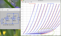
Try this model. A 6AQ5 is basically a 6V6 in a 7 pin miniature bottle.Do any of you have the Spice model of the 6AQ5 Triode?
Code:
*
* Generic triode model: 6V6T
* Copyright 2003--2008 by Ayumi Nakabayashi, All rights reserved.
* Version 3.10, Generated on Sat Mar  8 22:41:04 2008
*            Plate
*            | Grid
*            | | Cathode
*            | | |
.SUBCKT 6V6T A G K
BGG   GG   0 V=V(G,K)+0.99999998
BM1   M1   0 V=(0.048335289*(URAMP(V(A,K))+1e-10))**-0.77023894
BM2   M2   0 V=(0.6607234*(URAMP(V(GG)+URAMP(V(A,K))/7.0192317)+1e-10))**2.2702389
BP    P    0 V=0.0010053341*(URAMP(V(GG)+URAMP(V(A,K))/10.623555)+1e-10)**1.5
BIK   IK   0 V=U(V(GG))*V(P)+(1-U(V(GG)))*0.00060166202*V(M1)*V(M2)
BIG   IG   0 V=0.00051429562*URAMP(V(G,K))**1.5*(URAMP(V(G,K))/(URAMP(V(A,K))+URAMP(V(G,K)))*1.2+0.4)
BIAK  A    K I=URAMP(V(IK,IG)-URAMP(V(IK,IG)-(0.00061491868*URAMP(V(A,K))**1.5)))+1e-10*V(A,K)
BIGK  G    K I=V(IG)
* CAPS
CGA   G    A 4p
CGK   G    K 5p
CAK   A    K 6.9p
.ENDSHi all
Some new models of mine:
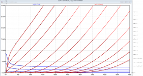
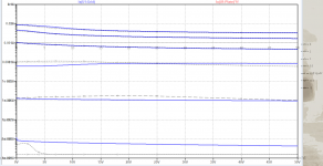
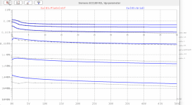
12AT7EH.i5 - in difference to the older i4 model of this tube, the curves are now measured not manually, but with my iTracer. Note that this tube turned out as one with quite close tolerances.
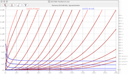
PC97.i5 - in difference to the older i4 model of this tube, the i5 mimics much better the remote cutoff behavior. See green marked zone in the attached graph. This tube might be interesting for AGC circuits (signal compressors).
BR Adrian
Some new models of mine:
12AT7EH.i5 - in difference to the older i4 model of this tube, the curves are now measured not manually, but with my iTracer. Note that this tube turned out as one with quite close tolerances.
PC97.i5 - in difference to the older i4 model of this tube, the i5 mimics much better the remote cutoff behavior. See green marked zone in the attached graph. This tube might be interesting for AGC circuits (signal compressors).
BR Adrian
Code:
*12AT7EH LTspice model based on the generic triode model from Adrian Immler, version i5
*A version log is at the end of this file
*100h BurnIn of 8 electro-harmonix factory tubes, sample selection and measurements done in March 2020
*Params fitted to the measured values by Adrian Immler, March 2022
*The high fit quality is presented at adrianimmler.simplesite.com
*History's best of tube describing art (plus some new ideas) is merged to this new approach.
*@ neg. Vg, Ia accuracy is similar to Koren models, and unrivaled for remote cutoff triodes
*@ small neg. Vg, the "Anlauf" current is considered.
*@ pos. Vg, Ig and Ia accuracy is on an unrivaled level (including neg. Va range!)
*This offers new simulation possibilities like grid resistor bias, backward plate modulated stages,
*Audion radio circuits, low voltage amps, guitar distortion stages or pulsed stages.
*            EH=electrode construction used by electro-harmonix
*            |     anode (plate)
*            |     | grid
*            |     | | cathode
*            |     | | |
.subckt 12AT7EH.i5 A G K
+ params:
*Parameters for space charge current Is (100% assigned to Ia @ Vg < 0)
+ mu   = 58    ;Determines the voltage gain @ constant Ia
+ rad  = 8k8   ;Differential anode resistance, set @ Iad and Vg=0V
+ Vct  = -0.2  ;Offsets the Ia-traces on the Va axis. Electrode material's contact potential
+ kp   = 240   ;Mimics the island effect
+ xs   = 1.5   ;Determines the curve of the Ia traces. Typically between 1.2 and 1.8
+ kIsr = 52m   ;Va-independent part of the Is reduction when grid current occurs
+ kvdg  = 110  ;Va-dependent part of the Is reduction when grid current occurs
*
*Parameters for assigning the space charge current to Ia and Ig @ Vg > 0
+ kB   = 0.2   ;Describes how fast Ia drops to zero when Va approaches zero.
+ radl = 850   ;Differential resistance for the Ia emission limit @ very small Va and Vg > 0
+ tsh  = 8     ;Ia transmission sharpness from 1st to 2nd Ia area. Keep between 3 and 20. Start with 20.
+ xl   = 1.3   ;Exponent for the emission limit
*
*Parameters of the grid-cathode vacuum diode
+ kg = 1850    ;Inverse scaling factor for the Va independent part of Ig (caution - interacts with xg!)
+ Vctg = -0.3  ;Offsets the log Ig-traces on the Vg axis. Electrode material's contact potential
+ xg   = 1.5   ;Determines the curve of the Ig slope versus (positive) Vg and Va >> 0
+ VT   = 0.098 ;Log(Ig) slope @ Vg<0. VT=k/q*Tk (cathodes absolute temp, typically 1150K)
+ rTr  = 0.5   ;ratio of VT for Igr. Typically 0.8
+ kVT  = 10m   ;Va dependent coeff. of VT
+ gft1 = 0     ;reduces the steering voltage around Vg=-Vg0, for finetuning purposes
+ gft1a= 1     ;reduces the steering voltage around Vg=-Vg0. Effect decreases with 1/(1+kB*Va)
+ gft2 = 0     ;finetunes the Igr drop @ increasing Va and around Vg=-Vg0
*
*Parameters for the caps
+ cag  = 1p6   ;From datasheet
+ cak  = 0p4   ;From datasheet
+ cgk  = 2p5   ;From datasheet
*
*special purpose parameters
+ os = 1       ;Overall scaling factor, if a user wishes to simulate manufacturing tolerances
+ murc = 10    ;Mu of the remote cutoff triode
+ ksrc = 10G   ;Inverse Iarc gain factor for the remote cutoff triode
+ kprc = 1k    ;Mimics the island effect for the remote cutoff triode
+ Vbatt = 0    ;heater battery voltage for direct heated battery triodes
+ Vdrmax = 100 ;max voltage of internal Vg drop, for convergence improvements
*
*Calculated parameters
+ Iad = {100/rad} ;Ia where the anode a.c. resistance is set according to rad.
+ ks = {pow(mu/(rad*xs*Iad**(1-1/xs)),-xs)} ;Reduces the unwished xs influence to the Ia slope
+ ksnom = {pow(mu/(rad*1.5*Iad**(1-1/1.5)),-1.5)} ;Sub-equation for calculating Vg0
+ Vg0 = {Vct + (Iad*ks)**(1/xs) - (Iad*ksnom)**(2/3)} ;Reduces the xs influence to Vct.
+ kl = {pow(1/(radl*xl*Ild**(1-1/xl)),-xl)} ;Reduces the xl influence to the Ia slope @ small Va
+ Ild = {sqrt(radl)*1m} ;Current where the Il a.c. resistance is set according to radl.
*
*Space charge current model
Rak A K 100G ;avoids "floating net" errors
Bft   ft 0 V=1/(1+pow(2*abs(v(G,Ki)+Vg0),3)) ;an auxiliary voltage to finetune the triode around Vg=-Vg0
Bggi GGi 0 V=(v(Gi,Ki)+Vg0)*(1/(1+kIsr*max(0, v(G,Ki)+Vg0))) - gft1*v(ft) - gft1a*v(ft)/(1+kB*v(Ahc)) ;Effective internal grid voltage.
Bahc Ahc 0 V=uramp(v(A,Ki)) ;Anode voltage, hard cut to zero @ neg. value
Bst   St 0 V=uramp(max(v(GGi)+v(A,Ki)/(mu), v(A,Ki)/kp*ln(1+exp(kp*(1/mu+v(GGi)/(1+v(Ahc)))))));Steering volt.
Bs    Ai Ki I=os/ks*pow(v(St),xs) ;Langmuir-Childs law for the space charge current Is
*Bstrc Strc 0 V=uramp(max(v(GGi)+v(Ahc)/(murc), v(Ahc)/kprc*ln(1+exp(kprc*(1/murc+v(GGi)/(1+v(Ahc)))))));FOR REMOTE CUTOFF TUBES ONLY
*Bsrc   Ai Ki I=os/ksrc*pow(v(Strc),xs) ;FOR REMOTE CUTOFF TUBES ONLY
*
*Anode current limit @ small Va
.func smin(z,y,k) {pow(pow(z+1f, -k)+pow(y+1f, -k), -1/k)} ;Min-function with smooth trans.
.func ssmin(z,y,k) {min(min(z,y), smin(z*1.003,y*1.003,k))};smin-function which suppresses small residual differences
Ra  A Ai 1
Bgl Gi A I=uramp(i(Ra)-ssmin(1/kl*pow(v(Ahc),xl),i(Ra),tsh)) ;Ia emission limit
*
*Grid model
Rgk G K 10G ;avoids "floating net" errors
Bvdg G Gi I=1/kvdg*pow(v(G,Gi),1.5) ;Reduces the internal effective grid voltage when Ig rises
Bcoh G Gi I=pow(uramp(v(G,Gi)-Vdrmax),2) ;A convergence help which softly limits the internal Vg voltage drop.
Rgip G Gi 1G ;avoids some warnings
.func fVT() {VT*exp(-kVT*sqrt(v(A,Ki)))}
.func Ivd(Vvd, kvd, xvd, VTvd)  {if(Vvd < 3, 1/kvd*pow(VTvd*xvd*ln(1+exp(Vvd/VTvd/xvd)),xvd), 1/kvd*pow(Vvd, xvd))} ;Vacuum diode function
Bgvd G Ki I=Ivd(v(G,Ki) + Vctg + min(0,v(A,Ki)/mu), kg/os, xg, fVT()) ;limits the internal Vg for convergence reasons
Bstn Stn 0 V=v(GGi)+min(0,v(A,Ki))/mu ;special steering voltage, sensitive to negative Anode voltages only
Bgr Gi Ai I= ivd(v(Stn),ks/os, xs, rTr*fVT())/(1+(kB+v(ft)*gft2)*v(Ahc));Is reflection to grid when Va approaches zero
*Bgr Gi Ai I=(ivd(v(Stn),ks/os, xs, rTr*fVT())+os/ksrc*pow(v(GGi),xs))/(1+(kB+v(ft)*gft2)*v(Ahc));FOR REMOTE CUTOFF TUBES ONLY
Bs0 Ai Ki  I=uramp(ivd(v(Stn),ks/os, xs, rTr*fVT()) - os/ks*pow(v(Stn),xs))
Bbatt Ki K V=Vbatt/2 ;for battery heated triodes; Offsets the average cathode potential to the half heater battery voltage
*
*Caps
C1 A G {cag}
C2 A K {cak}
C3 G K {cgk}
.ends
*
*Version log
*i1 :Initial version
*i2 :Pin order changed to the more common order A G K (Thanks to Markus Gyger for his tip)
*i3 :bugfix of the Ivd-function: now also usable for larger Vvd
*i4: Rgi replaced by a virtual vacuum diode (better convergence). ft1 deleted (no longer needed)
;2 new params for Ig finetuning @ Va and Vg near zero. New overall scaling factor os for aging etc.
*i5: improved convergence performance. PosVg/NegVa area now correct. Also accurate now for remote cutoff triodes!
Code:
*PC97 LTspice model based on the generic triode model from Adrian Immler, version i5
*A version log is at the end of this file
*100h BurnIn of 4 Valvo, 1 Siemens and 1 Telefunken tubes, sample selection and measurements done in April 2021
*Params fitted to the measured values by Adrian Immler, Dec. 2021
*The high fit quality is presented at adrianimmler.simplesite.com
*History's best of tube describing art (plus some new ideas) is merged to this new approach.
*@ neg. Vg, Ia accuracy is similar to Koren models, and unrivaled for remote cutoff triodes
*@ small neg. Vg, the "Anlauf" current is considered.
*@ pos. Vg, Ig and Ia accuracy is on an unrivaled level (including neg. Va range!)
*This offers new simulation possibilities like grid resistor bias, backward plate modulated stages,
*Audion radio circuits, low voltage amps, guitar distortion stages or pulsed stages.
*All PC97 electrode designs found so far were identical => manufacturer not mentioned in the suffix
*            i5 version
*            |  anode (plate)
*            |  | grid
*            |  | | cathode
*            |  | | |
.subckt PC97.i5 A G K
+ params:
*Parameters for space charge current Is (100% assigned to Ia @ Vg < 0)
+ mu   = 82.3  ;Determines the voltage gain @ constant Ia
+ rad  = 4k25  ;Differential anode resistance, set @ Iad and Vg=0V
+ Vct  = 0.165 ;Offsets the Ia-traces on the Va axis. Electrode material's contact potential
+ kp   = 300   ;Mimics the island effect
+ xs   = 1.55  ;Determines the curve of the Ia traces. Typically between 1.2 and 1.8
+ kIsr = 85m   ;Va-indepedent part of the Is reduction when grid current occurs
+ kvdg  = 68   ;Va-depedent part of the Is reduction when grid current occurs
*
*Parameters for assigning the space charge current to Ia and Ig @ Vg > 0
+ kB   = 0.6   ;Describes how fast Ia drops to zero when Va approaches zero.
+ radl = 680   ;Differential resistance for the Ia emission limit @ very small Va and Vg > 0
+ tsh  = 12    ;Ia transmission sharpness from 1st to 2nd Ia area. Keep between 3 and 20. Start with 20.
+ xl   = 1.3   ;Exponent for the emission limit
*
*Parameters of the grid-cathode vacuum diode
+ kg = 390     ;Inverse scaling factor for the Va independent part of Ig (caution - interacts with xg!)
+ Vctg = -0.25 ;Offsets the log Ig-traces on the Vg axis. Electrode material's contact potential
+ xg   = 1.25  ;Determines the curve of the Ig slope versus (positive) Vg and Va >> 0
+ VT   = 0.128 ;Log(Ig) slope @ Vg<0. VT=k/q*Tk (cathodes absolute temp, typically 1150K)
+ rTr  = 0.6   ;ratio of VT for Igr. Typically 0.8
+ kVT=04m      ;Va dependant koeff. of VT
+ gft1 = 0.05  ;reduces the steering voltage around Vg=-Vg0, for finetuning purposes
+ gft1a= 0.3   ;reduces the steering voltage around Vg=-Vg0. Effect decreases with 1/(1+kB*Va)
+ gft2 = 2     ;finetunes the Igr drop @ increasing Va and around Vg=-Vg0
*
*Parameters for the caps
+ cag  = 0p48  ;From datasheet
+ cak  = 0p21  ;From datasheet
+ cgk  = 3p2   ;From datasheet
*
*special purpose parameters
+ os = 1       ;Overall scaling factor, if a user wishes to simulate manufacturing tolerances
+ murc = 29.5  ;Mu of the remote cutoff triode
+ ksrc = 5k    ;Inverse Iarc gain factor for the remote cutoff triode
+ kprc = 1k    ;Mimics the island effect for the remote cutoff triode
+ Vbatt = 0    ;heater battery voltage for direct heated battery triodes
+ Vdrmax = 100 ;max voltage of internal Vg drop, for convergence improvements
*
*Calculated parameters
+ Iad = {100/rad} ;Ia where the anode a.c. resistance is set according to rad.
+ ks = {pow(mu/(rad*xs*Iad**(1-1/xs)),-xs)} ;Reduces the unwished xs influence to the Ia slope
+ ksnom = {pow(mu/(rad*1.5*Iad**(1-1/1.5)),-1.5)} ;Sub-equation for calculating Vg0
+ Vg0 = {Vct + (Iad*ks)**(1/xs) - (Iad*ksnom)**(2/3)} ;Reduces the xs influence to Vct.
+ kl = {pow(1/(radl*xl*Ild**(1-1/xl)),-xl)} ;Reduces the xl influence to the Ia slope @ small Va
+ Ild = {sqrt(radl)*1m} ;Current where the Il a.c. resistance is set according to radl.
*
*Space charge current model
Rak A K 100G ;avoids "floating net" errors
Bft   ft 0 V=1/(1+pow(2*abs(v(G,Ki)+Vg0),3)) ;an auxiliary voltage to finetune the triode around Vg=-Vg0
Bggi GGi 0 V=(v(Gi,Ki)+Vg0)*(1/(1+kIsr*max(0, v(G,Ki)+Vg0))) - gft1*v(ft) - gft1a*v(ft)/(1+kB*v(Ahc)) ;Effective internal grid voltage.
Bahc Ahc 0 V=uramp(v(A,Ki)) ;Anode voltage, hard cut to zero @ neg. value
Bst   St 0 V=uramp(max(v(GGi)+v(A,Ki)/(mu), v(A,Ki)/kp*ln(1+exp(kp*(1/mu+v(GGi)/(1+v(Ahc)))))));Steering volt.
Bs    Ai Ki I=os/ks*pow(v(St),xs) ;Langmuir-Childs law for the space charge current Is
Bstrc Strc 0 V=uramp(max(v(GGi)+v(Ahc)/(murc), v(Ahc)/kprc*ln(1+exp(kprc*(1/murc+v(GGi)/(1+v(Ahc)))))));FOR REMOTE CUTOFF TUBES ONLY
Bsrc   Ai Ki I=os/ksrc*pow(v(Strc),xs) ;FOR REMOTE CUTOFF TUBES ONLY
*
*Anode current limit @ small Va
.func smin(z,y,k) {pow(pow(z+1f, -k)+pow(y+1f, -k), -1/k)} ;Min-function with smooth trans.
.func ssmin(z,y,k) {min(min(z,y), smin(z*1.003,y*1.003,k))};smin-function which suppresses small residual differencies
Ra  A Ai 1
Bgl Gi A I=uramp(i(Ra)-ssmin(1/kl*pow(v(Ahc),xl),i(Ra),tsh)) ;Ia emission limit
*
*Grid model
Rgk G K 10G ;avoids "floating net" errors
Bvdg G Gi I=1/kvdg*pow(v(G,Gi),1.5) ;Reduces the internal effective grid voltage when Ig rises
Bcoh G Gi I=pow(uramp(v(G,Gi)-Vdrmax),2) ;A convergence help which softly limits the internal Vg voltage drop.
Rgip G Gi 1G ;avoids some warnings
.func fVT() {VT*exp(-kVT*sqrt(v(A,Ki)))}
.func Ivd(Vvd, kvd, xvd, VTvd)  {if(Vvd < 3, 1/kvd*pow(VTvd*xvd*ln(1+exp(Vvd/VTvd/xvd)),xvd), 1/kvd*pow(Vvd, xvd))} ;Vacuum diode function
Bgvd G Ki I=Ivd(v(G,Ki) + Vctg + min(0,v(A,Ki)/mu), kg/os, xg, fVT()) ;limits the internal Vg for convergence reasons
Bstn Stn 0 V=v(GGi)+min(0,v(A,Ki))/mu ;special steering voltage, sensitive to negative Anode voltages only
*Bgr Gi Ai I= ivd(v(Stn),ks/os, xs, rTr*fVT())/(1+(kB+v(ft)*gft2)*v(Ahc));Is reflection to grid when Va approaches zero
Bgr Gi Ai I=(ivd(v(Stn),ks/os, xs, rTr*fVT())+os/ksrc*pow(v(GGi),xs))/(1+(kB+v(ft)*gft2)*v(Ahc));FOR REMOTE CUTOFF TUBES ONLY
Bs0 Ai Ki  I=uramp(ivd(v(Stn),ks/os, xs, rTr*fVT()) - os/ks*pow(v(Stn),xs))
Bbatt Ki K V=Vbatt/2 ;for battery heated triodes; Offsets the average cathode potential to the half heater battery voltage
*
*Caps
C1 A G {cag}
C2 A K {cak}
C3 G K {cgk}
.ends
*
*Version log
*i1 :Initial version
*i2 :Pin order changed to the more common order A G K (Thanks to Markus Gyger for his tip)
*i3 :bugfix of the Ivd-function: now also usable for larger Vvd
*i4: Rgi replaced by a virtual vacuum diode (better convergence). ft1 deleted (no longer needed)
;2 new params for Ig finetuning @ Va and Vg near zero. New overall scaling factor os for aging etc.
*i5: improved convergence performance. PosVg/NegVa area now correct. Also accurate now for remote cutoff triodes!
Attachments
Hi all
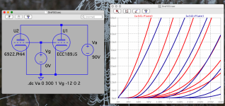
As announced, here the ECC189.i5 model.
Cheers!
As announced, here the ECC189.i5 model.
Cheers!
Code:
*ECC189 LTspice model based on the generic triode model from Adrian Immler, version i5
*A version log is at the end of this file
*100h BurnIn of 5 Siemens tubes, sample selection and measurements done in April 2022
*Params fitted to the measured values by Adrian Immler, April 2022
*The high fit quality is presented at adrianimmler.simplesite.com
*History's best of tube describing art (plus some new ideas) is merged to this new approach.
*@ neg. Vg, Ia accuracy is similar to Koren models, and unrivaled for remote cutoff triodes
*@ small neg. Vg, the "Anlauf" current is considered.
*@ pos. Vg, Ig and Ia accuracy is on an unrivaled level (including neg. Va range!)
*This offers new simulation possibilities like grid resistor bias, backward plate modulated stages,
*Audion radio circuits, low voltage amps, guitar distortion stages or pulsed stages.
*All ECC189 electrode designs found so far were identical => manufacturer not mentioned in the suffix
*              i5 version
*              |  anode (plate)
*              |  | grid
*              |  | | cathode
*              |  | | |
.subckt ECC189.i5 A G K
+ params:
*Parameters for space charge current Is (100% assigned to Ia @ Vg < 0)
+ mu   = 46.4  ;Determines the voltage gain @ constant Ia
+ rad  = 1k15  ;Differential anode resistance, set @ Iad and Vg=0V
+ Vct  = 0.31  ;Offsets the Ia-traces on the Va axis. Electrode material's contact potential
+ kp   = 100   ;Mimics the island effect
+ xs   = 1.5   ;Determines the curve of the Ia traces. Typically between 1.2 and 1.8
+ kIsr = 300m  ;Va-independent part of the Is reduction when grid current occurs
+ kvdg  = 70   ;Va-dependent part of the Is reduction when grid current occurs
*
*Parameters for assigning the space charge current to Ia and Ig @ Vg > 0
+ kB   = 1.5   ;Describes how fast Ia drops to zero when Va approaches zero.
+ radl = 150   ;Differential resistance for the Ia emission limit @ very small Va and Vg > 0
+ tsh  = 20    ;Ia transmission sharpness from 1st to 2nd Ia area. Keep between 3 and 20. Start with 20.
+ xl   = 1.5   ;Exponent for the emission limit
*
*Parameters of the grid-cathode vacuum diode
+ kg = 300     ;Inverse scaling factor for the Va independent part of Ig (caution - interacts with xg!)
+ Vctg = -0.2  ;Offsets the log Ig-traces on the Vg axis. Electrode material's contact potential
+ xg   = 1.1   ;Determines the curve of the Ig slope versus (positive) Vg and Va >> 0
+ VT   = 0.144 ;Log(Ig) slope @ Vg<0. VT=k/q*Tk (cathodes absolute temp, typically 1150K)
+ rTr  = 0.6   ;ratio of VT for Igr. Typically 0.8
+ kVT=20m      ;Va dependent koeff. of VT
+ gft1 = 0.09  ;reduces the steering voltage around Vg=-Vg0, for finetuning purposes
+ gft1a= 0.4   ;reduces the steering voltage around Vg=-Vg0. Effect decreases with 1/(1+kB*Va)
+ gft2 = 0     ;finetunes the Igr drop @ increasing Va and around Vg=-Vg0
*
*Parameters for the caps
+ cag  = 1p9   ;From datasheet
+ cak  = 1p7   ;From datasheet
+ cgk  = 3p5   ;From datasheet
*
*special purpose parameters
+ os = 1       ;Overall scaling factor, if a user wishes to simulate manufacturing tolerances
+ murc = 10    ;Mu of the remote cutoff triode
+ ksrc = 5k85  ;Inverse Iarc gain factor for the remote cutoff triode
+ kprc = 55    ;Mimics the island effect for the remote cutoff triode
+ Vbatt = 0    ;heater battery voltage for direct heated battery triodes
+ Vdrmax = 100 ;max voltage of internal Vg drop, for convergence improvements
*
*Calculated parameters
+ Iad = {100/rad} ;Ia where the anode a.c. resistance is set according to rad.
+ ks = {pow(mu/(rad*xs*Iad**(1-1/xs)),-xs)} ;Reduces the unwished xs influence to the Ia slope
+ ksnom = {pow(mu/(rad*1.5*Iad**(1-1/1.5)),-1.5)} ;Sub-equation for calculating Vg0
+ Vg0 = {Vct + (Iad*ks)**(1/xs) - (Iad*ksnom)**(2/3)} ;Reduces the xs influence to Vct.
+ kl = {pow(1/(radl*xl*Ild**(1-1/xl)),-xl)} ;Reduces the xl influence to the Ia slope @ small Va
+ Ild = {sqrt(radl)*1m} ;Current where the Il a.c. resistance is set according to radl.
*
*Space charge current model
Rak A K 100G ;avoids "floating net" errors
Bft   ft 0 V=1/(1+pow(2*abs(v(G,Ki)+Vg0),3)) ;an auxiliary voltage to finetune the triode around Vg=-Vg0
Bggi GGi 0 V=(v(Gi,Ki)+Vg0)*(1/(1+kIsr*max(0, v(G,Ki)+Vg0))) - gft1*v(ft) - gft1a*v(ft)/(1+kB*v(Ahc)) ;Effective internal grid voltage.
Bahc Ahc 0 V=uramp(v(A,Ki)) ;Anode voltage, hard cut to zero @ neg. value
Bst   St 0 V=uramp(max(v(GGi)+v(A,Ki)/(mu), v(A,Ki)/kp*ln(1+exp(kp*(1/mu+v(GGi)/(1+v(Ahc)))))));Steering volt.
Bs    Ai Ki I=os/ks*pow(v(St),xs) ;Langmuir-Childs law for the space charge current Is
Bstrc Strc 0 V=uramp(max(v(GGi)+v(Ahc)/(murc), v(Ahc)/kprc*ln(1+exp(kprc*(1/murc+v(GGi)/(1+v(Ahc)))))));FOR REMOTE CUTOFF TUBES ONLY
Bsrc   Ai Ki I=os/ksrc*pow(v(Strc),xs) ;FOR REMOTE CUTOFF TUBES ONLY
*
*Anode current limit @ small Va
.func smin(z,y,k) {pow(pow(z+1f, -k)+pow(y+1f, -k), -1/k)} ;Min-function with smooth trans.
.func ssmin(z,y,k) {min(min(z,y), smin(z*1.003,y*1.003,k))};smin-function which suppresses small residual differences
Ra  A Ai 1
Bgl Gi A I=uramp(i(Ra)-ssmin(1/kl*pow(v(Ahc),xl),i(Ra),tsh)) ;Ia emission limit
*
*Grid model
Rgk G K 10G ;avoids "floating net" errors
Bvdg G Gi I=1/kvdg*pow(v(G,Gi),1.5) ;Reduces the internal effective grid voltage when Ig rises
Bcoh G Gi I=pow(uramp(v(G,Gi)-Vdrmax),2) ;A convergence help which softly limits the internal Vg voltage drop.
Rgip G Gi 1G ;avoids some warnings
.func fVT() {VT*exp(-kVT*sqrt(v(A,Ki)))}
.func Ivd(Vvd, kvd, xvd, VTvd)  {if(Vvd < 3, 1/kvd*pow(VTvd*xvd*ln(1+exp(Vvd/VTvd/xvd)),xvd), 1/kvd*pow(Vvd, xvd))} ;Vacuum diode function
Bgvd G Ki I=Ivd(v(G,Ki) + Vctg + min(0,v(A,Ki)/mu), kg/os, xg, fVT()) ;limits the internal Vg for convergence reasons
Bstn Stn 0 V=v(GGi)+min(0,v(A,Ki))/mu ;special steering voltage, sensitive to negative Anode voltages only
*Bgr Gi Ai I= ivd(v(Stn),ks/os, xs, rTr*fVT())/(1+(kB+v(ft)*gft2)*v(Ahc));Is reflection to grid when Va approaches zero
Bgr Gi Ai I=(ivd(v(Stn),ks/os, xs, rTr*fVT())+os/ksrc*pow(v(GGi),xs))/(1+(kB+v(ft)*gft2)*v(Ahc));FOR REMOTE CUTOFF TUBES ONLY
Bs0 Ai Ki  I=uramp(ivd(v(Stn),ks/os, xs, rTr*fVT()) - os/ks*pow(v(Stn),xs))
Bbatt Ki K V=Vbatt/2 ;for battery heated triodes; Offsets the average cathode potential to the half heater battery voltage
*
*Caps
C1 A G {cag}
C2 A K {cak}
C3 G K {cgk}
.ends
*
*Version log
*i1 :Initial version
*i2 :Pin order changed to the more common order A G K (Thanks to Markus Gyger for his tip)
*i3 :bugfix of the Ivd-function: now also usable for larger Vvd
*i4: Rgi replaced by a virtual vacuum diode (better convergence). ft1 deleted (no longer needed)
;2 new params for Ig finetuning @ Va and Vg near zero. New overall scaling factor os for aging etc.
*i5: improved convergence performance. PosVg/NegVa area now correct. Also accurate now for remote cutoff triodes!
Attachments
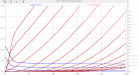
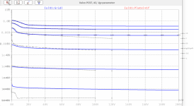
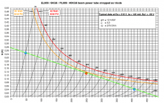
Apparently ECC189 is the notorious 6ES8, which was sold by somebody or other as a 6DJ8 back in the 1980s, and caused all sorts of confusion. IIRC, there was an article titled something like "The Suitability of the 6DJ8 for Audio" in which a 6ES8 was mistaken for a 6DJ8, tested, and found to be 'inferior' for use as a common cathode voltage amplifier for audio.
Not that there is anything wrong with an ECC189/6ES8. It's just not a 6DJ8.
Not that there is anything wrong with an ECC189/6ES8. It's just not a 6DJ8.
Thanks for that important hint, Rongon. I attached a comparison graph, so everybody can see the BIG difference.
BTW, I did a typo in #3270. I wanted (and still want!) to say that the 6N24P is a sharp cutoff triode, but just took the wrong word...
BTW, I did a typo in #3270. I wanted (and still want!) to say that the 6N24P is a sharp cutoff triode, but just took the wrong word...
Attachments
I think you mean message #1445. But this is probably a word-wrapping problem. The model seems to work for me. Try this:
Code:
* cx-301a LTSpice model
.subckt cx-301a P G K
+ params: ccg=3.1p cgp=8.1p ccp=2.2p rgi=1000
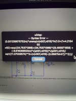
Bp P K I=(0.001258676752m)*uramp(V(P,K)*ln(1.0+(14.21540262)+exp((34.75371389)+(34.75371389)*((8.485971858)+(-8.616268503m)*V(G,K))*V(G,K)/sqrt((11.07009574)**2+(V(P,K)-(2.05875447))**2)))/(34.75371389))**(1.88212582)
rcp 1 3 1g
c1 2 3 {ccg}
c2 1 2 {cgp}
c3 1 3 {ccp}
r1 2 5 {rgi}
d3 6 3 dx
.model dx d(is=1n rs=1 cjo=1pf tt=1n)
.ends cx-301aNormal I don't build a separate model for triode, as you'll get triode mode when you connect grid 2 to plate. Here is specific triode model based on the curve found here: http://www.dissident-audio.com/Yves/EL509-Triode.gif
.SUBCKT EL509_T 1 2 3 ; Plate Grid Cathode
E1 7 0 VALUE={V(1,3)/KP*LOG(1+EXP(KP*(1/MU+(VCT+V(2,3))/SQRT(KVB+V(1,3)*V(1,3)))))}
RE1 7 0 1G ; TO AVOID FLOATING NODES
G1 1 3 VALUE={(PWR(V(7),EX)+PWRS(V(7),EX))/KG1}
RCP 1 3 1G ; TO AVOID FLOATING NODES
C1 2 3 {CCG} ; CATHODE-GRID
C2 2 1 {CGP} ; GRID=PLATE
C3 1 3 {CCP} ; CATHODE-PLATE
D3 5 3 DX ; POSITIVE GRID CURRENT
R1 2 5 {RGI} ; POSITIVE GRID CURRENT
.MODEL DX D(IS=1N RS=1 CJO=10PF TT=1N)
.ENDS
*$
- www.dmitrynizh.com/tubeparams_image.htm
- Plate Curves image file: EL509_TF-T.png
- Data source link:
.SUBCKT EL509_T 1 2 3 ; Plate Grid Cathode
- PARAMS: CCG=3P CGP=1.4P CCP=1.9P RGI=2000
- MU=3.733 KG1=202.18 KP=34.44 KVB=9.38 VCT=-1.883 EX=1.303
- Vp_MAX=500 Ip_MAX=500 Vg_step=10 Vg_start=0 Vg_count=16
- Rp=4000 Vg_ac=55 P_max=40 Vg_qui=-48 Vp_qui=300
- X_MIN=68 Y_MIN=43 X_SIZE=809 Y_SIZE=486 FSZ_X=1296 FSZ_Y=736 XYGrid=false
- showLoadLine=n showIp=y isDHT=n isPP=n isAsymPP=n showDissipLimit=y
- showIg1=n gridLevel2=n isInputSnapped=n
- XYProjections=n harmonicPlot=n dissipPlot=n
E1 7 0 VALUE={V(1,3)/KP*LOG(1+EXP(KP*(1/MU+(VCT+V(2,3))/SQRT(KVB+V(1,3)*V(1,3)))))}
RE1 7 0 1G ; TO AVOID FLOATING NODES
G1 1 3 VALUE={(PWR(V(7),EX)+PWRS(V(7),EX))/KG1}
RCP 1 3 1G ; TO AVOID FLOATING NODES
C1 2 3 {CCG} ; CATHODE-GRID
C2 2 1 {CGP} ; GRID=PLATE
C3 1 3 {CCP} ; CATHODE-PLATE
D3 5 3 DX ; POSITIVE GRID CURRENT
R1 2 5 {RGI} ; POSITIVE GRID CURRENT
.MODEL DX D(IS=1N RS=1 CJO=10PF TT=1N)
.ENDS
*$
Attachments

This is brilliant, thank you so much Koonw for your help!Normal I don't build a separate model for triode, as you'll get triode mode when you connect grid 2 to plate. Here is specific triode model based on the curve found here: http://www.dissident-audio.com/Yves/EL509-Triode.gif
*----------------------------------------------------------------------------------
- www.dmitrynizh.com/tubeparams_image.htm
- Plate Curves image file: EL509_TF-T.png
- Data source link:
.SUBCKT EL509_T 1 2 3 ; Plate Grid Cathode
- PARAMS: CCG=3P CGP=1.4P CCP=1.9P RGI=2000
- MU=3.733 KG1=202.18 KP=34.44 KVB=9.38 VCT=-1.883 EX=1.303
*----------------------------------------------------------------------------------
- Vp_MAX=500 Ip_MAX=500 Vg_step=10 Vg_start=0 Vg_count=16
- Rp=4000 Vg_ac=55 P_max=40 Vg_qui=-48 Vp_qui=300
- X_MIN=68 Y_MIN=43 X_SIZE=809 Y_SIZE=486 FSZ_X=1296 FSZ_Y=736 XYGrid=false
- showLoadLine=n showIp=y isDHT=n isPP=n isAsymPP=n showDissipLimit=y
- showIg1=n gridLevel2=n isInputSnapped=n
- XYProjections=n harmonicPlot=n dissipPlot=n
E1 7 0 VALUE={V(1,3)/KP*LOG(1+EXP(KP*(1/MU+(VCT+V(2,3))/SQRT(KVB+V(1,3)*V(1,3)))))}
RE1 7 0 1G ; TO AVOID FLOATING NODES
G1 1 3 VALUE={(PWR(V(7),EX)+PWRS(V(7),EX))/KG1}
RCP 1 3 1G ; TO AVOID FLOATING NODES
C1 2 3 {CCG} ; CATHODE-GRID
C2 2 1 {CGP} ; GRID=PLATE
C3 1 3 {CCP} ; CATHODE-PLATE
D3 5 3 DX ; POSITIVE GRID CURRENT
R1 2 5 {RGI} ; POSITIVE GRID CURRENT
.MODEL DX D(IS=1N RS=1 CJO=10PF TT=1N)
.ENDS
*$
I'm getting syntax errors, probably due to the bullets in the model. Can you re-post the model using the forum's "Code" feature? Thanks.Normal I don't build a separate model for triode, as you'll get triode mode when you connect grid 2 to plate. Here is specific triode model based on the curve found here: http://www.dissident-audio.com/Yves/EL509-Triode.gif
- Home
- Amplifiers
- Tubes / Valves
- Vacuum Tube SPICE Models