Hi euro21
You can easily calulate the plate voltages for all 10 tubes: Ua = 582V - 39k1*Ia
Yes, I agree, the anode power loss is a problem in your stage as currently proposed. Well, for the short moment of my measurement it is not a problem, but one should not run a tube longer time out of spec. Good amp designs (where the tubes runs for years without problems) consider a margin to the max allowed power of at least 25%. Such a margin adresses the sample tolerances as well as the aging of a tube, which reduces slowly the plate current over time (with the side effect of increased plate losses in your stage)
BR Adrian
BTW when you use my model instead of a datasheet based one, your design gets more margin!
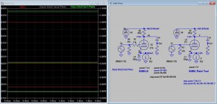
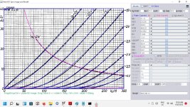
In #3200 post the picture in the right shows the no. 10 tube at 9.97mA current.
39k*9.97mA= 388.83V
So the anode voltage is 582-388.83= 193.17V which is perfect.
The simulation at this constant current shows 244.5V, the 39k loaded simulated tube voltage is 227.16V.

Are you sure that these voltages are fine, or something in the simulation is wrong?
39k*9.97mA= 388.83V
So the anode voltage is 582-388.83= 193.17V which is perfect.
The simulation at this constant current shows 244.5V, the 39k loaded simulated tube voltage is 227.16V.
Are you sure that these voltages are fine, or something in the simulation is wrong?
Attachments
I know, but I didn't choose this operating point. ") I'm guessing that Adrian ran his tests using the values in the schematic in your post # 3192 for the sake of comparison. But this circuit operates the tube at the limits of its maximum ratings. As Adrian pointed out, you can run the tube this way for short periods of testing but it is not safe for continuous operation.
I'm guessing that Adrian ran his tests using the values in the schematic in your post # 3192 for the sake of comparison. But this circuit operates the tube at the limits of its maximum ratings. As Adrian pointed out, you can run the tube this way for short periods of testing but it is not safe for continuous operation.
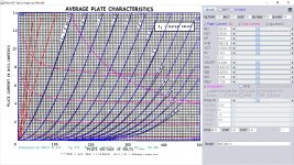
Going back to your schematic in post # 3187, if you want to use a B+ of 300 volts instead of 582 you should be able to find an operating point that is more reasonable. Using a 300 volt B+ supply, a plate resistor of 39k and a cathode resistor of 300 ohms gives a workable operating point for this tube. The plate current is around 3.4 mA or so at a plate voltage of about 167 volts and a grid voltage of about -1 volt. See attached. All of the operating parameters are well within the tube's maximum ratings. If you want to use an active (constant current source) load instead of the fixed resistor, set it at about 3.4 mA and you should be fine.

Of course, this isn't the only possible operating point. It's just an example of one that should work.
I'm guessing that Adrian ran his tests using the values in the schematic in your post # 3192 for the sake of comparison. But this circuit operates the tube at the limits of its maximum ratings. As Adrian pointed out, you can run the tube this way for short periods of testing but it is not safe for continuous operation.Going back to your schematic in post # 3187, if you want to use a B+ of 300 volts instead of 582 you should be able to find an operating point that is more reasonable. Using a 300 volt B+ supply, a plate resistor of 39k and a cathode resistor of 300 ohms gives a workable operating point for this tube. The plate current is around 3.4 mA or so at a plate voltage of about 167 volts and a grid voltage of about -1 volt. See attached. All of the operating parameters are well within the tube's maximum ratings. If you want to use an active (constant current source) load instead of the fixed resistor, set it at about 3.4 mA and you should be fine.
Of course, this isn't the only possible operating point. It's just an example of one that should work.
Ray, this schematic "not mine", I don't want to build it, but working one from net:
https://www.audio-talk.co.uk/phpBB2/viewtopic.php?f=11&t=4983
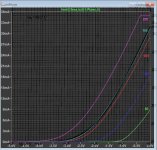
10mA, -1V is stable working point of this tube, with 200V Ua.
Simulated Ua exceed this voltage by the huge margin. Why?
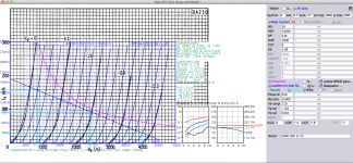
As I wrote one earlier post, simulated curves are very perfect ones, seems that each covers datasheet curve, where grid voltage greater by 0.5V (not -1V, rather -1.5V) than simulated curve.
https://www.audio-talk.co.uk/phpBB2/viewtopic.php?f=11&t=4983
10mA, -1V is stable working point of this tube, with 200V Ua.
Simulated Ua exceed this voltage by the huge margin. Why?
As I wrote one earlier post, simulated curves are very perfect ones, seems that each covers datasheet curve, where grid voltage greater by 0.5V (not -1V, rather -1.5V) than simulated curve.
I myself would not run the 6AM4 at this operating point (200 Vp-k at 10 mA), regardless of whether the grid voltage is -1 volt or -1.5 volts. That is a plate dissipation of 2 watts, which is the maximum rating for that tube. The link you provided also acknowledged that. You can expect short tube life and even some outright tube failures pushing a tube that hard.
As for the SPICE model curves vs. the datasheet curves, I think Adrian has explained this as well as he can. But if the tube you end up using behaves more like Adrian's model than the datasheet, then you will push the tube well beyond its rating. Maybe someone here who has experience with the 6AM4 can offer an opinion about running the 6AM4 that hard. But I admit to being conservative when it comes to component ratings so I personally wouldn't be comfortable doing this.
At this point, I think you just have to decide whether you trust the schematic enough to build it as shown or not. Simulation can only take you so far.
Good luck.
I build this 6AM4 model based on GE curve which is most popular and more linear, (grid current data borrowed from Adrians, it is high):
Code:
**** 6AM4 ** Advanced Grid Current **********************************
* Created on 01/22/2022 11:07 using paint_kit.jar 3.1
* www.dmitrynizh.com/tubeparams_image.htm
* Plate Curves image file: 6am4.jpg
* Data source link:
*----------------------------------------------------------------------------------
.SUBCKT 6AM4 1 2 3 ; Plate Grid Cathode
+ PARAMS: CCG=4.6P  CGP=1.4P CCP=2.4P
+ MU=104.34 KG1=238.09 KP=252.5 KVB=1883.29 VCT=-0.004125 EX=1.317
+ VGOFF=-0.3431 IGA=0.002742 IGB=0.04791 IGC=13.54 IGEX=1.724
* Vp_MAX=500 Ip_MAX=14 Vg_step=0.5 Vg_start=1.5 Vg_count=16
* Rp=4000 Vg_ac=55 P_max=2 Vg_qui=-48 Vp_qui=300
* X_MIN=68 Y_MIN=43 X_SIZE=788 Y_SIZE=556 FSZ_X=1296 FSZ_Y=736 XYGrid=false
* showLoadLine=n showIp=y isDHT=n isPP=n isAsymPP=n showDissipLimit=y
* showIg1=y gridLevel2=y isInputSnapped=n
* XYProjections=n harmonicPlot=n dissipPlot=n
*----------------------------------------------------------------------------------
E1 7 0 VALUE={V(1,3)/KP*LOG(1+EXP(KP*(1/MU+(VCT+V(2,3))/SQRT(KVB+V(1,3)*V(1,3)))))}
RE1 7 0 1G  ; TO AVOID FLOATING NODES
G1 1 3 VALUE={(PWR(V(7),EX)+PWRS(V(7),EX))/KG1}
RCP 1 3 1G   ; TO AVOID FLOATING NODES
C1 2 3 {CCG} ; CATHODE-GRID
C2 2 1 {CGP} ; GRID=PLATE
C3 1 3 {CCP} ; CATHODE-PLATE
RE2 2 0 1G
EGC 8 0 VALUE={V(2,3)-VGOFF} ; POSITIVE GRID THRESHOLD
GG 2 3 VALUE={(IGA+IGB/(IGC+V(1,3)))*(MU/KG1)*(PWR(V(8),IGEX)+PWRS(V(8),IGEX))}
.ENDS
*$
Attachments
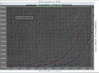
Mu or Gm*Rl of the samples is higher than that of original data.10mA, -1V is stable working point of this tube, with 200V Ua.
Simulated Ua exceed this voltage by the huge margin. Why?
Hi euro21In #3200 post the picture in the right shows the no. 10 tube at 9.97mA current.
39k*9.97mA= 388.83V
So the anode voltage is 582-388.83= 193.17V which is perfect.
The simulation at this constant current shows 244.5V, the 39k loaded simulated tube voltage is 227.16V.
Are you sure that these voltages are fine, or something in the simulation is wrong?
Once more: My Model reflects the TYPICAL behaviour of the 10 tubes I measured. You took No.10 for comarison, which is one of the most extreme tube out of my lot. With the same kind of logic, one can do a comarison with the tube No.9, and then (because of the big difference between Sim and No.9) set a questionmark behind a datasheet based model whether it really reflects reality...
However...
Thank you Koonw for your model, as this will hopefully set an end to this pointless discussion.
Hi I made 2 PSpice models for DA250 DHT power triode. Maybe it was inside the topic i didnt check ?
Anyway it is not big help, because these tubes are almost imposibile to find
one model is plain triode model, another is with DHT connection pins.
cheers
.
** DA250 PLATE CHRS Composite DHT ***************************************
.SUBCKT DA250_DHT 1 2 3 4 ; P G K1 K2
RFIL_LEFT 3 31 {RFIL/4}
RFIL_RIGHT 4 41 {RFIL/4}
RFIL_MIDDLE1 31 34 {RFIL/4}
RFIL_MIDDLE2 34 41 {RFIL/4}
E11 32 0 VALUE={V(1,31)/KP*LOG(1+EXP(KP*(1/MU+V(2,31)/SQRT(KVB+V(1,31)*V(1,31)))))}
E12 42 0 VALUE={V(1,41)/KP*LOG(1+EXP(KP*(1/MU+V(2,41)/SQRT(KVB+V(1,41)*V(1,41)))))}
RE11 32 0 1G
RE12 42 0 1G
G11 1 31 VALUE={(PWR(V(32),EX)+PWRS(V(32),EX))/(2*KG1)}
G12 1 41 VALUE={(PWR(V(42),EX)+PWRS(V(42),EX))/(2*KG1)}
RCP1 1 34 1G
C1 2 34 {CCG} ; CATHODE-GRID
C2 2 1 {CGP} ; GRID=PLATE
C3 1 34 {CCP} ; CATHODE-PLATE
D3 5 3 DX ; FOR GRID CURRENT
D4 6 4 DX ; FOR GRID CURRENT
RG1 2 5 {2*RGI} ; FOR GRID CURRENT
RG2 2 6 {2*RGI} ; FOR GRID CURRENT
.MODEL DX D(IS=1N RS=1 CJO=10PF TT=1N)
.ENDS DA250_DHT
*$
** DA250 PLATE CHRS ****************************************
.SUBCKT DA250 1 2 3 ; Plate Grid Cathode
E1 7 0 VALUE={V(1,3)/KP*LOG(1+EXP(KP*(1/MU+(VCT+V(2,3))/SQRT(KVB+V(1,3)*V(1,3)))))}
RE1 7 0 1G ; TO AVOID FLOATING NODES
G1 1 3 VALUE={(PWR(V(7),EX)+PWRS(V(7),EX))/KG1}
RCP 1 3 1G ; TO AVOID FLOATING NODES
C1 2 3 {CCG} ; CATHODE-GRID
C2 2 1 {CGP} ; GRID=PLATE
C3 1 3 {CCP} ; CATHODE-PLATE
D3 5 3 DX ; POSITIVE GRID CURRENT
R1 2 5 {RGI} ; POSITIVE GRID CURRENT
.MODEL DX D(IS=1N RS=1 CJO=10PF TT=1N)
.ENDS DA250
*$
?Anyway it is not big help, because these tubes are almost imposibile to find
one model is plain triode model, another is with DHT connection pins.
cheers
.
** DA250 PLATE CHRS Composite DHT ***************************************
- Created on 01/23/2022 14:22 using paint_kit.jar 3.1
- www.dmitrynizh.com/tubeparams_image.htm
- Plate Curves image file: /Users/zoran/Desktop/Model_Paint_Tools/Graph/DA250 plate chrs.jpg
- Data source link:
.SUBCKT DA250_DHT 1 2 3 4 ; P G K1 K2
- PARAMS: CCG=21P CGP=41P CCP=6P RFIL=5
- MU=16 KG1=14040 KP=536 KVB=1000 VCT=0 EX=1.96 RGI=2000
- Vp_MAX=5000 Ip_MAX=300 Vg_step=31.5 Vg_start=0 Vg_count=10
- Rp=25000 Vg_ac=110 P_max=250 Vg_qui=-126 Vp_qui=2450
- X_MIN=50 Y_MIN=173 X_SIZE=750 Y_SIZE=464 FSZ_X=1684 FSZ_Y=803 XYGrid=true
- showLoadLine=y showIp=y isDHT=y isPP=n isAsymPP=n showDissipLimit=y
- showIg1=n gridLevel2=n isInputSnapped=n
- XYProjections=y harmonicPlot=y dissipPlot=y
RFIL_LEFT 3 31 {RFIL/4}
RFIL_RIGHT 4 41 {RFIL/4}
RFIL_MIDDLE1 31 34 {RFIL/4}
RFIL_MIDDLE2 34 41 {RFIL/4}
E11 32 0 VALUE={V(1,31)/KP*LOG(1+EXP(KP*(1/MU+V(2,31)/SQRT(KVB+V(1,31)*V(1,31)))))}
E12 42 0 VALUE={V(1,41)/KP*LOG(1+EXP(KP*(1/MU+V(2,41)/SQRT(KVB+V(1,41)*V(1,41)))))}
RE11 32 0 1G
RE12 42 0 1G
G11 1 31 VALUE={(PWR(V(32),EX)+PWRS(V(32),EX))/(2*KG1)}
G12 1 41 VALUE={(PWR(V(42),EX)+PWRS(V(42),EX))/(2*KG1)}
RCP1 1 34 1G
C1 2 34 {CCG} ; CATHODE-GRID
C2 2 1 {CGP} ; GRID=PLATE
C3 1 34 {CCP} ; CATHODE-PLATE
D3 5 3 DX ; FOR GRID CURRENT
D4 6 4 DX ; FOR GRID CURRENT
RG1 2 5 {2*RGI} ; FOR GRID CURRENT
RG2 2 6 {2*RGI} ; FOR GRID CURRENT
.MODEL DX D(IS=1N RS=1 CJO=10PF TT=1N)
.ENDS DA250_DHT
*$
** DA250 PLATE CHRS ****************************************
- Created on 01/23/2022 14:44 using paint_kit.jar 3.1
- www.dmitrynizh.com/tubeparams_image.htm
- Plate Curves image file: /Users/zoran/Desktop/Model_Paint_Tools/Graph/DA250 plate chrs.jpg
- Data source link:
.SUBCKT DA250 1 2 3 ; Plate Grid Cathode
- PARAMS: CCG=21P CGP=41P CCP=6P RGI=2000
- MU=16 KG1=14040 KP=536 KVB=1000 VCT=0 EX=1.96
- Vp_MAX=5000 Ip_MAX=300 Vg_step=15.75 Vg_start=0 Vg_count=17
- Rp=25000 Vg_ac=110 P_max=250 Vg_qui=-126 Vp_qui=2450
- X_MIN=49 Y_MIN=173 X_SIZE=752 Y_SIZE=464 FSZ_X=1616 FSZ_Y=749 XYGrid=true
- showLoadLine=y showIp=y isDHT=n isPP=n isAsymPP=n showDissipLimit=y
- showIg1=n gridLevel2=n isInputSnapped=n
- XYProjections=y harmonicPlot=y dissipPlot=y
E1 7 0 VALUE={V(1,3)/KP*LOG(1+EXP(KP*(1/MU+(VCT+V(2,3))/SQRT(KVB+V(1,3)*V(1,3)))))}
RE1 7 0 1G ; TO AVOID FLOATING NODES
G1 1 3 VALUE={(PWR(V(7),EX)+PWRS(V(7),EX))/KG1}
RCP 1 3 1G ; TO AVOID FLOATING NODES
C1 2 3 {CCG} ; CATHODE-GRID
C2 2 1 {CGP} ; GRID=PLATE
C3 1 3 {CCP} ; CATHODE-PLATE
D3 5 3 DX ; POSITIVE GRID CURRENT
R1 2 5 {RGI} ; POSITIVE GRID CURRENT
.MODEL DX D(IS=1N RS=1 CJO=10PF TT=1N)
.ENDS DA250
*$
Attachments
Thanks Koonw.I build this 6AM4 model based on GE curve
Try this PC88 model:
Code:
* Plate Curves image file: pc88.jpg
* Data source link:
*----------------------------------------------------------------------------------
.SUBCKT PC88 1 2 3 ; Plate Grid Cathode
+ PARAMS: CCG=3.8P  CGP=1.2P CCP=0.055P
+ MU=71.72 KG1=232.05 KP=438.5 KVB=466.33 VCT=0.3582 EX=1.365
+ VGOFF=-0.6 IGA=2E-4 IGB=0.054 IGC=9.92 IGEX=1.64
* Vp_MAX=300 Ip_MAX=40 Vg_step=0.5 Vg_start=0 Vg_count=9
* Rp=4000 Vg_ac=55 P_max=2 Vg_qui=-48 Vp_qui=300
* X_MIN=28 Y_MIN=34 X_SIZE=805 Y_SIZE=538 FSZ_X=1296 FSZ_Y=736 XYGrid=false
* showLoadLine=n showIp=y isDHT=n isPP=n isAsymPP=n showDissipLimit=y
* showIg1=y gridLevel2=y isInputSnapped=n
* XYProjections=n harmonicPlot=n dissipPlot=n
*----------------------------------------------------------------------------------
E1 7 0 VALUE={V(1,3)/KP*LOG(1+EXP(KP*(1/MU+(VCT+V(2,3))/SQRT(KVB+V(1,3)*V(1,3)))))}
RE1 7 0 1G  ; TO AVOID FLOATING NODES
G1 1 3 VALUE={(PWR(V(7),EX)+PWRS(V(7),EX))/KG1}
RCP 1 3 1G   ; TO AVOID FLOATING NODES
C1 2 3 {CCG} ; CATHODE-GRID
C2 2 1 {CGP} ; GRID=PLATE
C3 1 3 {CCP} ; CATHODE-PLATE
RE2 2 0 1G
EGC 8 0 VALUE={V(2,3)-VGOFF} ; POSITIVE GRID THRESHOLD
GG 2 3 VALUE={(IGA+IGB/(IGC+V(1,3)))*(MU/KG1)*(PWR(V(8),IGEX)+PWRS(V(8),IGEX))}
.ENDS
*$
Attachments
Hi all
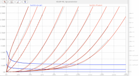
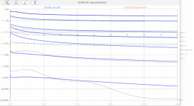
Here is a spice model of mine for the Russian 6S19P. It is intended for regulated power supplies, but may be something for a small OTL amp. Or one can even design a crazy "backward plate modulated" stage, for those looking for something different.
However, please note that my small lot of 8 tubes showed a widely variating island-effect. So, for larger Va voltages (say > 100V) the sim might be quite different compared to the running tube.
In addition, all tubes showed a cathode area which is not covered by the grid (near the getter), which means that there is a small vacuum diode from plate to cathode, in parallel to the triode. Thus, there is a small plate current of some mA, which you can't suppress with the grid !!
BR Adrian
Here is a spice model of mine for the Russian 6S19P. It is intended for regulated power supplies, but may be something for a small OTL amp. Or one can even design a crazy "backward plate modulated" stage, for those looking for something different
.However, please note that my small lot of 8 tubes showed a widely variating island-effect. So, for larger Va voltages (say > 100V) the sim might be quite different compared to the running tube.
In addition, all tubes showed a cathode area which is not covered by the grid (near the getter), which means that there is a small vacuum diode from plate to cathode, in parallel to the triode. Thus, there is a small plate current of some mA, which you can't suppress with the grid !!
BR Adrian
Code:
*6S19P LTspice model based on the generic triode model from Adrian Immler, version i5
*A version log is at the end of this file
*100h BurnIn of 8 Ulyanovsk factory tubes, sample selection and measurements done in Jan 2022
*Params fitted to the measured values by Adrian Immler, Febr 2022
*This model is accurate for Vg up to 8V.
*The high fit quality is presented at adrianimmler.simplesite.com
*History's best of tube decribing art (plus some new ideas) is merged to this new approach.
*@ neg. Vg, Ia accuracy is similar to Koren models, and unrivaled for remote cutoff triodes
*@ small neg. Vg, the "Anlauf" current is considered.
*@ pos. Vg, Ig and Ia accuracy is on a unrivaled level (including neg. Va range!)
*This offers new simulation possibilities like grid resistor bias, backward plate modulated stages,
*Audion radio circuits, low voltage amps, guitar distortion stages or pulsed stages.
*             i5 version of the generic triode model
*             |  anode (plate)
*             |  | grid
*             |  | | cathode
*             |  | | |
.subckt 6S19P.i5 A G K
+ params:
*Parameters for space charge current Is (100% assigned to Ia @ Vg < 0)
+ mu   = 4.8   ;Determines the voltage gain @ constant Ia
+ rad  = 178   ;Differential anode resistance, set @ Iad and Vg=0V
+ Vct  = 0.8   ;Offsets the Ia-traces on the Va axis. Electrode material's contact potential
+ kp   = 9.5   ;Mimics the island effect
+ xs   = 1.5   ;Determines the curve of the Ia traces. Typically between 1.2 and 1.8
+ kIsr = 0     ;Va-indepedent part of the Is reduction when gridcurrent occurs
+ kvdg  = 130  ;Va-depedent part of the Is reduction when gridcurrent occurs
*
*Parameters for assigning the space charge current to Ia and Ig @ Vg > 0
+ kB   = 0.4   ;Describes how fast Ia drops to zero when Va approaches zero.
+ radl = 95    ;Differential resistance for the Ia emission limit @ very small Va and Vg > 0
+ tsh  = 12    ;Ia transmission sharpness from 1th to 2nd Ia area. Keep between 3 and 20. Start with 20.
+ xl   = 1.3   ;Exponent for the emission limit
*
*Parameters of the grid-cathode vacuum diode
+ kg = 1k02    ;Inverse scaling factor for the Va independent part of Ig (caution - interacts with xg!)
+ Vctg = -0.2  ;Offsets the log Ig-traces on the Vg axis. Electrode material's contact potential
+ xg   = 1.5   ;Determines the curve of the Ig slope versus (positive) Vg and Va >> 0
+ VT   = 0.15  ;Log(Ig) slope @ Vg<0. VT=k/q*Tk (cathodes absolute temp, typically 1150K)
+ rTr  = 0.7   ;ratio of VT for Igr. Typically 0.8
+ kVT  = 60m   ;Va dependant koeff. of VT
+ gft1 = 0     ;reduces the steering voltage around Vg=-Vg0, for finetuning purposes
+ gft1a= 0.6   ;reduces the steering voltage around Vg=-Vg0. Effect decreases with 1/(1+kB*Va)
+ gft2 = 4     ;finetunes the Igr drop @ incrasing Va and around Vg=-Vg0
*
*Parameters for the caps
+ cag  = 8p    ;From datasheet
+ cak  = 2p5   ;From datasheet
+ cgk  = 6p5   ;From datasheet
*
*special purpose parameters
+ os = 1       ;Overall scaling factor, if a user wishes to simulate manufacturing tolerances
+ murc = 10    ;Mu of the remote cutoff triode
+ ksrc = 10G   ;Inverse Iarc gain factor for the remote cuttoff triode
+ kprc = 1k    ;Mimics the island effect for the remote cotoff triode
+ Vbatt = 0    ;heater battery voltage for direct heated battery triodes
+ Vdrmax = 100 ;max voltage of internal Vg drop, for convergence improvements
*
*Calculated parameters
+ Iad = {100/rad} ;Ia where the anode a.c. resistance is set according to rad.
+ ks = {pow(mu/(rad*xs*Iad**(1-1/xs)),-xs)} ;Reduces the unwished xs influence to the Ia slope
+ ksnom = {pow(mu/(rad*1.5*Iad**(1-1/1.5)),-1.5)} ;Sub-equation for calculating Vg0
+ Vg0 = {Vct + (Iad*ks)**(1/xs) - (Iad*ksnom)**(2/3)} ;Reduces the xs influence to Vct.
+ kl = {pow(1/(radl*xl*Ild**(1-1/xl)),-xl)} ;Reduces the xl influence to the Ia slope @ small Va
+ Ild = {sqrt(radl)*1m} ;Current where the Il a.c. resistance is set according to radl.
*
*plate-cathode vacuum diode model
*(special enhancement for 6S19P only, as there is a small cathode-plate track without grid)
Bvdak A K I=12u*pow(v(A,K),xs)
*Space charge current model
Rak A K 100G ;avoids "floating net" errors
Bft   ft 0 V=1/(1+pow(2*abs(v(G,Ki)+Vg0),3)) ;an auxiliary voltage to finetune the triode around Vg=-Vg0
Bggi GGi 0 V=(v(Gi,Ki)+Vg0)*(1/(1+kIsr*max(0, v(G,Ki)+Vg0))) - gft1*v(ft) - gft1a*v(ft)/(1+kB*v(Ahc)) ;Effective internal grid voltage.
Bahc Ahc 0 V=uramp(v(A,Ki)) ;Anode voltage, hard cut to zero @ neg. value
Bst   St 0 V=uramp(max(v(GGi)+v(A,Ki)/(mu), v(A,Ki)/kp*ln(1+exp(kp*(1/mu+v(GGi)/(1+v(Ahc)))))));Steering volt.
Bs    Ai Ki I=os/ks*pow(v(St),xs) ;Langmuir-Childs law for the space charge current Is
*Bstrc Strc 0 V=uramp(max(v(GGi)+v(Ahc)/(murc), v(Ahc)/kprc*ln(1+exp(kprc*(1/murc+v(GGi)/(1+v(Ahc)))))));FOR REMOTE CUTOFF TUBES ONLY
*Bsrc   Ai Ki I=os/ksrc*pow(v(Strc),xs) ;FOR REMOTE CUTOFF TUBES ONLY
*
*Anode current limit @ small Va
.func smin(z,y,k) {pow(pow(z+1f, -k)+pow(y+1f, -k), -1/k)} ;Min-function with smooth trans.
.func ssmin(z,y,k) {min(min(z,y), smin(z*1.003,y*1.003,k))};smin-function which suppresses small residual differencies
Ra  A Ai 1
Bgl Gi A I=uramp(i(Ra)-ssmin(1/kl*pow(v(Ahc),xl),i(Ra),tsh)) ;Ia emission limit
*
*Grid model
Rgk G K 10G ;avoids "floating net" errors
Bvdg G Gi I=1/kvdg*pow(v(G,Gi),1.5) ;Reduces the internal effective grid voltage when Ig rises
Bcoh G Gi I=pow(uramp(v(G,Gi)-Vdrmax),2) ;A convergence help which softly limits the internal Vg voltage drop.
Rgip G Gi 1G ;avoids some warnings
.func fVT() {VT*exp(-kVT*sqrt(v(A,Ki)))}
.func Ivd(Vvd, kvd, xvd, VTvd)  {if(Vvd < 3, 1/kvd*pow(VTvd*xvd*ln(1+exp(Vvd/VTvd/xvd)),xvd), 1/kvd*pow(Vvd, xvd))} ;Vacuum diode function
Bgvd G Ki I=Ivd(v(G,Ki) + Vctg + min(0,v(A,Ki)/mu), kg/os, xg, fVT()) ;limits the internal Vg for convergence reasons
Bstn Stn 0 V=v(GGi)+min(0,v(A,Ki))/mu ;special steering voltage, sensitive to negative Anodevoltages only
Bgr Gi Ai I= ivd(v(Stn),ks/os, xs, rTr*fVT())/(1+(kB+v(ft)*gft2)*v(Ahc));Is reflection to grid when Va approaches zero
*Bgr Gi Ai I=(ivd(v(Stn),ks/os, xs, rTr*fVT())+os/ksrc*pow(v(GGi),xs))/(1+(kB+v(ft)*gft2)*v(Ahc));FOR REMOTE CUTOFF TUBES ONLY
Bs0 Ai Ki  I=uramp(ivd(v(Stn),ks/os, xs, rTr*fVT()) - os/ks*pow(v(Stn),xs))
Bbatt Ki K V=Vbatt/2 ;for battery heated triodes; Offsets the average cathode potential to the half heater battery voltage
*
*Caps
C1 A G {cag}
C2 A K {cak}
C3 G K {cgk}
.ends
*
*Version log
*i1 :Initial version
*i2 :Pin order changed to the more common order A G K (Thanks to Markus Gyger for his tip)
*i3 :bugfix of the Ivd-function: now also usable for larger Vvd
*i4: Rgi replaced by a virtual vacuum diode (better convergence). ft1 deleted (no longer needed)
;2 new prarams for Ig finetuning @ Va and Vg near zero. New overall skaling factor os for aging etc.
*i5: improved convergence performance. PosVg/NegVa area now correct. Also accurate now for remote cutoff triodes!
Attachments
Here are the Ayumi models for the 6U8:
Triode section:
Pentode section:
Pentode section, triode connected:
Triode section:
Code:
*
* Generic triode model: 6U8T
* Copyright 2003--2008 by Ayumi Nakabayashi, All rights reserved.
* Version 3.10, Generated on Sat Mar  8 22:41:00 2008
*            Plate
*            | Grid
*            | | Cathode
*            | | |
.SUBCKT 6U8T A G K
BGG   GG   0 V=V(G,K)+0.99995916
BM1   M1   0 V=(0.035181787*(URAMP(V(A,K))+1e-10))**-2.5690962
BM2   M2   0 V=(0.36863223*(URAMP(V(GG)+URAMP(V(A,K))/17.94587)+1e-10))**4.0690962
BP    P    0 V=0.0033085897*(URAMP(V(GG)+URAMP(V(A,K))/48.682314)+1e-10)**1.5
BIK   IK   0 V=U(V(GG))*V(P)+(1-U(V(GG)))*0.013182953*V(M1)*V(M2)
BIG   IG   0 V=0.0016542949*URAMP(V(G,K))**1.5*(URAMP(V(G,K))/(URAMP(V(A,K))+URAMP(V(G,K)))*1.2+0.4)
BIAK  A    K I=URAMP(V(IK,IG)-URAMP(V(IK,IG)-(0.0017567609*URAMP(V(A,K))**1.5)))+1e-10*V(A,K)
BIGK  G    K I=V(IG)
* CAPS
CGA   G    A 1.8p
CGK   G    K 2.8p
CAK   A    K 2p
.ENDS
Pentode section:
Code:
*
* Generic pentode model: 6U8P
* Copyright 2003--2008 by Ayumi Nakabayashi, All rights reserved.
* Version 3.10, Generated on Sat Mar  8 22:41:03 2008
*            Plate
*            | Screen Grid
*            | |  Control Grid
*            | |  |  Cathode
*            | |  |  |
.SUBCKT 6U8P A G2 G1 K
BGG   GG   0 V=V(G1,K)+0.65071871
BM1   M1   0 V=(0.046006989*(URAMP(V(G2,K))+1e-10))**-2.7651713
BM2   M2   0 V=(0.35168575*(URAMP(V(GG)+URAMP(V(G2,K))/14.091647)))**4.2651713
BP    P    0 V=0.003445744*(URAMP(V(GG)+URAMP(V(G2,K))/40.068859))**1.5
BIK   IK   0 V=U(V(GG))*V(P)+(1-U(V(GG)))*0.018698107*V(M1)*V(M2)
BIG   IG   0 V=0.001722872*URAMP(V(G1,K))**1.5*(URAMP(V(G1,K))/(URAMP(V(A,K))+URAMP(V(G1,K)))*1.2+0.4)
BIK2  IK2  0 V=V(IK,IG)*(1-0.4*(EXP(-URAMP(V(A,K))/URAMP(V(G2,K))*15)-EXP(-15)))
BIG2T IG2T 0 V=V(IK2)*(0.74580496*(1-URAMP(V(A,K))/(URAMP(V(A,K))+10))**1.5+0.25419504)
BIK3  IK3  0 V=V(IK2)*(URAMP(V(A,K))+6302.5)/(URAMP(V(G2,K))+6302.5)
BIK4  IK4  0 V=V(IK3)-URAMP(V(IK3)-(0.0018526668*(URAMP(V(A,K))+URAMP(URAMP(V(G2,K))-URAMP(V(A,K))))**1.5))
BIP   IP   0 V=URAMP(V(IK4,IG2T)-URAMP(V(IK4,IG2T)-(0.0018526668*URAMP(V(A,K))**1.5)))
BIAK  A    K I=V(IP)+1e-10*V(A,K)
BIG2  G2   K I=URAMP(V(IK4,IP))
BIGK  G1   K I=V(IG)
* CAPS
CGA   G1  A  0.007p
CGK   G1  K  3p
C12   G1  G2 2p
CAK   A   K  3.5p
.ENDS
Pentode section, triode connected:
Code:
*
* Generic triode model: 6U8PT
* Copyright 2003--2008 by Ayumi Nakabayashi, All rights reserved.
* Version 3.10, Generated on Sat Mar  8 22:41:03 2008
*             Plate
*             | Grid
*             | | Cathode
*             | | |
.SUBCKT 6U8PT A G K
BGG   GG   0 V=V(G,K)+0.65071871
BM1   M1   0 V=(0.046006989*(URAMP(V(A,K))+1e-10))**-2.7651713
BM2   M2   0 V=(0.35168575*(URAMP(V(GG)+URAMP(V(A,K))/14.091647)+1e-10))**4.2651713
BP    P    0 V=0.003445744*(URAMP(V(GG)+URAMP(V(A,K))/40.068859)+1e-10)**1.5
BIK   IK   0 V=U(V(GG))*V(P)+(1-U(V(GG)))*0.018698107*V(M1)*V(M2)
BIG   IG   0 V=0.001722872*URAMP(V(G,K))**1.5*(URAMP(V(G,K))/(URAMP(V(A,K))+URAMP(V(G,K)))*1.2+0.4)
BIAK  A    K I=URAMP(V(IK,IG)-URAMP(V(IK,IG)-(0.0018526668*URAMP(V(A,K))**1.5)))+1e-10*V(A,K)
BIGK  G    K I=V(IG)
* CAPS
CGA   G    A 2p
CGK   G    K 3p
CAK   A    K 3.5p
.ENDS
Last edited:
Hi, I want to take the time to learn how to use LT Spice. My son used it in college he says he'll help me get going, even though he eventually went into IT not electronics. I understand that the LT Spice installer doesn't come with tube models.
Would someone point me at some download links to get the tube models? And any other tube-related models LT might be lacking, OPT's maybe, not sure if getting the tubes is all I need right off. Thanks a lot.
Would someone point me at some download links to get the tube models? And any other tube-related models LT might be lacking, OPT's maybe, not sure if getting the tubes is all I need right off. Thanks a lot.
- Home
- Amplifiers
- Tubes / Valves
- Vacuum Tube SPICE Models