Thank you Koonw for the 6F12P pentode models.
I know this tube varies quite a bit between samples, so I won't take the simulation results as gospel. However, I do want something that comes close to real world results, at least for DC operating points, gain, and a general idea of linearity.
I've loaded up the 6F12P_NEW model and will give it a try.
Thanks again...
First, a merry Christmas to all of you! 
As I gift, here is my 6922EH.i5 model...
Beside of that, I still struggle to translate my i5 model into Spice compatible code. Several issues, for example how to define parameters which are calculated from other parameters etc. If in this community is a native Spice speaker, I would be glad for help!!
Thanks & enjoy the free Christmas time!
BR Adrian
As I gift, here is my 6922EH.i5 model...
Code:
*6922EH LTspice model based on the generic triode model from Adrian Immler, version i5
*A version log is at the end of this file
*100h BurnIn of 4 electro-harmonix factory tubes, sample selection and measurements done in April 2021
*Params fitted to the measured values by Adrian Immler, Nov 2021
*This model is accurate for Vg up to 2V.
*The high fit quality is presented at adrianimmler.simplesite.com
*History's best of tube decribing art (plus some new ideas) is merged to this new approach.
*@ neg. Vg, Ia accuracy is similar to Koren models, and unrivaled for remote cutoff triodes
*@ small neg. Vg, the "Anlauf" current is considered.
*@ pos. Vg, Ig and Ia accuracy is on a unrivaled level (including neg. Va range!)
*This offers new simulation possibilities like grid resistor bias, backward plate modulated stages,
*Audion radio circuits, low voltage amps, guitar distortion stages or pulsed stages.
*            EH=electrode construction used by electro-harmonix
*            |    anode (plate)
*            |    | grid
*            |    | | cathode
*            |    | | |
.subckt 6922EH.i5 A G K
+ params:
*Parameters for space charge current Is (100% assigned to Ia @ Vg < 0)
+ mu   = 32.8  ;Determines the voltage gain @ constant Ia
+ rad  = 1k8   ;Differential anode resistance, set @ Iad and Vg=0V
+ Vct  = 0.75  ;Offsets the Ia-traces on the Va axis. Electrode material's contact potential
+ kp   = 320   ;Mimics the island effect
+ xs   = 1.35  ;Determines the curve of the Ia traces. Typically between 1.2 and 1.8
+ kIsr = 20m   ;Va-indepedent part of the Is reduction when gridcurrent occurs
+ kvdg  = 150  ;Va-depedent part of the Is reduction when gridcurrent occurs
*
*Parameters for assigning the space charge current to Ia and Ig @ Vg > 0
+ kB   = 1.3   ;Describes how fast Ia drops to zero when Va approaches zero.
+ radl = 290   ;Differential resistance for the Ia emission limit @ very small Va and Vg > 0
+ tsh  = 6     ;Ia transmission sharpness from 1th to 2nd Ia area. Keep between 3 and 20. Start with 20.
+ xl   = 1.2   ;Exponent for the emission limit
*
*Parameters of the grid-cathode vacuum diode
+ kg = 760     ;Inverse scaling factor for the Va independent part of Ig (caution - interacts with xg!)
+ Vctg = 0.05  ;Offsets the log Ig-traces on the Vg axis. Electrode material's contact potential
+ xg   = 1.25  ;Determines the curve of the Ig slope versus (positive) Vg and Va >> 0
+ VT   = 0.15  ;Log(Ig) slope @ Vg<0. VT=k/q*Tk (cathodes absolute temp, typically 1150K)
+ rTr  = 1     ;ratio of VT for Igr. Typically 0.8
+ kVT  = 55m   ;Va dependant koeff. of VT
+ gft1 = 0     ;reduces the steering voltage around Vg=-Vg0, for finetuning purposes
+ gft1a= 0     ;reduces the steering voltage around Vg=-Vg=. Effect decreases with 1/(1+kB*Va)
+ gft2 = 2     ;finetunes the Igr drop @ incrasing Va and around Vg=-Vg0
*
*Parameters for the caps
+ cag  = 1p5   ;From datasheet
+ cak  = 2p0   ;From datasheet
+ cgk  = 3p25  ;From datasheet
*
*special purpose parameters
+ os = 1       ;Overall scaling factor, if a user wishes to simulate manufacturing tolerances
+ murc = 10    ;Mu of the remote cutoff triode
+ ksrc = 10G   ;Inverse Iarc gain factor for the remote cuttoff triode
+ kprc = 1k    ;Mimics the island effect for the remote cotoff triode
+ Vbatt = 0    ;heater battery voltage for direct heated battery triodes
+ Vdrmax = 1.35;max voltage of internal Vg drop, for convergence improvements
*
*Calculated parameters
+ Iad = {100/rad} ;Ia where the anode a.c. resistance is set according to rad.
+ ks = {pow(mu/(rad*xs*Iad**(1-1/xs)),-xs)} ;Reduces the unwished xs influence to the Ia slope
+ ksnom = {pow(mu/(rad*1.5*Iad**(1-1/1.5)),-1.5)} ;Sub-equation for calculating Vg0
+ Vg0 = {Vct + (Iad*ks)**(1/xs) - (Iad*ksnom)**(2/3)} ;Reduces the xs influence to Vct.
+ kl = {pow(1/(radl*xl*Ild**(1-1/xl)),-xl)} ;Reduces the xl influence to the Ia slope @ small Va
+ Ild = {sqrt(radl)*1m} ;Current where the Il a.c. resistance is set according to radl.
*
*Space charge current model
Rak A K 100G ;avoids "floating net" errors
Bft   ft 0 V=1/(1+pow(2*abs(v(G,Ki)+Vg0),3)) ;an auxiliary voltage to finetune the triode around Vg=-Vg0
Bggi GGi 0 V=(v(Gi,Ki)+Vg0)*(1/(1+kIsr*max(0, v(G,Ki)+Vg0))) - gft1*v(ft) - gft1a*v(ft)/(1+kB*v(Ahc)) ;Effective internal grid voltage.
Bahc Ahc 0 V=uramp(v(A,Ki)) ;Anode voltage, hard cut to zero @ neg. value
Bst   St 0 V=uramp(max(v(GGi)+v(A,Ki)/(mu), v(A,Ki)/kp*ln(1+exp(kp*(1/mu+v(GGi)/(1+v(Ahc)))))));Steering volt.
Bs    Ai Ki I=os/ks*pow(v(St),xs) ;Langmuir-Childs law for the space charge current Is
*Bstrc Strc 0 V=uramp(max(v(GGi)+v(Ahc)/(murc), v(Ahc)/kprc*ln(1+exp(kprc*(1/murc+v(GGi)/(1+v(Ahc)))))));FOR REMOTE CUTOFF TUBES ONLY
*Bsrc   Ai Ki I=os/ksrc*pow(v(Strc),xs) ;FOR REMOTE CUTOFF TUBES ONLY
*
*Anode current limit @ small Va
.func smin(z,y,k) {pow(pow(z+1f, -k)+pow(y+1f, -k), -1/k)} ;Min-function with smooth trans.
.func ssmin(z,y,k) {min(min(z,y), smin(z*1.003,y*1.003,k))};smin-function which suppresses small residual differencies
Ra  A Ai 1
Bgl Gi A I=uramp(i(Ra)-ssmin(1/kl*pow(v(Ahc),xl),i(Ra),tsh)) ;Ia emission limit
*
*Grid model
Rgk G K 10G ;avoids "floating net" errors
Bvdg G Gi I=1/kvdg*pow(v(G,Gi),1.5) ;Reduces the internal effective grid voltage when Ig rises
Bcoh G Gi I=pow(uramp(v(G,Gi)-Vdrmax),2) ;A convergence help which softly limits the internal Vg voltage drop.
Rgip G Gi 1G ;avoids some warnings
.func fVT() {VT*exp(-kVT*sqrt(v(A,Ki)))}
.func Ivd(Vvd, kvd, xvd, VTvd)  {if(Vvd < 3, 1/kvd*pow(VTvd*xvd*ln(1+exp(Vvd/VTvd/xvd)),xvd), 1/kvd*pow(Vvd, xvd))} ;Vacuum diode function
Bgvd G Ki I=Ivd(v(G,Ki) + Vctg + min(0,v(A,Ki)/mu), kg/os, xg, fVT()) ;limits the internal Vg for convergence reasons
Bstn Stn 0 V=v(GGi)+min(0,v(A,Ki))/mu ;special steering voltage, sensitive to negative Anodevoltages only
Bgr Gi Ai I= ivd(v(Stn),ks/os, xs, rTr*fVT())/(1+(kB+v(ft)*gft2)*v(Ahc));Is reflection to grid when Va approaches zero
*Bgr Gi Ai I=(ivd(v(Stn),ks/os, xs, rTr*fVT())+os/ksrc*pow(v(GGi),xs))/(1+(kB+v(ft)*gft2)*v(Ahc));FOR REMOTE CUTOFF TUBES ONLY
Bs0 Ai Ki  I=uramp(ivd(v(Stn),ks/os, xs, rTr*fVT()) - os/ks*pow(v(Stn),xs))
Bbatt Ki K V=Vbatt/2 ;for battery heated triodes; Offsets the average cathode potential to the half heater battery voltage
*
*Caps
C1 A G {cag}
C2 A K {cak}
C3 G K {cgk}
.ends
*
*Version log
*i1 :Initial version
*i2 :Pin order changed to the more common order A G K (Thanks to Markus Gyger for his tip)
*i3 :bugfix of the Ivd-function: now also usable for larger Vvd
*i4: Rgi replaced by a virtual vacuum diode (better convergence). ft1 deleted (no longer needed)
;2 new prarams for Ig finetuning @ Va and Vg near zero. New overall skaling factor os for aging etc.
*i5: improved convergence performance. PosVg/NegVa area now correct. Also accurate now for remote cutoff triodes!
Beside of that, I still struggle to translate my i5 model into Spice compatible code. Several issues, for example how to define parameters which are calculated from other parameters etc. If in this community is a native Spice speaker, I would be glad for help!!
Thanks & enjoy the free Christmas time!
BR Adrian
Attachments
Welcome, Ray!
BTW the 6N24P is a quite similar (if not identical) electrode construction like the electro-harmonix 6922. But with other pin order, and with the screen connected to one of the grids. I guess that's why it is so super cheap to buy. However, there are some circuits where a screen connected to the grid isn't a drawback (or even wished), like cascodes, constant current sinks, LTPI etc. So, when it comes to the 6922 in a circuit, I first asking me "will also the 6N24P do it?"")
All the best, Adrian
BTW the 6N24P is a quite similar (if not identical) electrode construction like the electro-harmonix 6922. But with other pin order, and with the screen connected to one of the grids. I guess that's why it is so super cheap to buy. However, there are some circuits where a screen connected to the grid isn't a drawback (or even wished), like cascodes, constant current sinks, LTPI etc. So, when it comes to the 6922 in a circuit, I first asking me "will also the 6N24P do it?"
All the best, Adrian
Hi Ron
Thanks for that hint - that is a mistake of mine, I meant the shield, but wrote screen...
BTW I just discovered a tipo of mine (caused by the auto-correction function), in # 3162, where I asked whether a native "spice" speaker may help me. I meant "Pspice". Recently, I was several times asked whether I could provide a Pspice compatible triode model. So I tried (and still do), but it is much more difficult than expected. Any help is appreciated!
BR Adrian
I wish I could help with the Pspice problem. I've never used it, unfortunately.
I was thinking about the grid and the shield -- I guess when wired as a cascode, the grid connected to the shield is the one that goes to the voltage divider? The triode with the grid connected to shield has to be the top triode then, I think.
I was thinking about the grid and the shield -- I guess when wired as a cascode, the grid connected to the shield is the one that goes to the voltage divider? The triode with the grid connected to shield has to be the top triode then, I think.
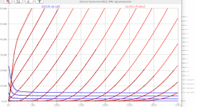
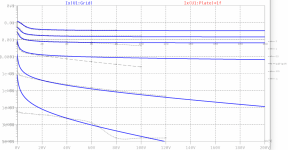
Hi Koonw, I tried this model and it did not work. Can you check and find what is wrong?Here 6V6GT GE model, original curve has triode, grid#1 and grid#2 current curve:
Code:**** 6V6GT ****************************************** * Created on 08/20/2021 15:48 using paint_kip.jar * [url=http://www.dmitrynizh.com/tubeparams_image.htm]Model Paint Tools: Trace Tube Parameters over Plate Curves, Interactively[/url] * Plate Curves image file: 6v6gt.png * Data source link: <plate curves URL> *---------------------------------------------------------------------------------- .SUBCKT 6V6GT P G2 G K ; LTSpice tetrode.asy pinout * .SUBCKT 6V6GT P G K G2 ; Koren Pentode Pspice pinout + PARAMS: MU=10.7 KG1=1676.38 KP=46.44 KVB=1412.81 VCT=-0.0399 EX=1.306 KG2=2635.52 KNEE=9.75 KVC=1.67 + KLAM=1.5E-9 KLAMG=1.35E-4 KD=0.02767 KC=0.2692 KR1=1.112E-5 KR2=0.06456 KVBG=0.01817 KB1=1.299 KB2=3.194 KB3=1.125E-5 KB4=0.98 KVBGI=3.975E-6 KNK=0.1559 KNG=0.00951 KNPL=1.145E-6 KNSL=3.87E-4 KNPR=0.4664 KNSR=84.99 + CCG=0.7P CGP=9P CCP=7.5P VGOFF=-3.6 IGA=8.688E-5 IGB=0.007008 IGC=15 IGEX=3.236 * Vp_MAX=500 Ip_MAX=140 Vg_step=5 Vg_start=0 Vg_count=14 * X_MIN=37 Y_MIN=25 X_SIZE=731 Y_SIZE=516 FSZ_X=1288 FSZ_Y=723 XYGrid=false * Rp=1400 Vg_ac=20 P_max=12 Vg_qui=-32.5 Vp_qui=300 * showLoadLine=n showIp=y isDHP=n isPP=n isAsymPP=n isUL=n showDissipLimit=y * showIg1=y isInputSnapped=y addLocalNFB=n * XYProjections=n harmonicPlot=y dissipPlot=n * UL=0.43 EG2=250 gridLevel2=y addKink=y isTanhKnee=n advSigmoid=y *---------------------------------------------------------------------------------- RE1 7 0 1G ; DUMMY SO NODE 7 HAS 2 CONNECTIONS E1 7 0 VALUE= ; E1 BREAKS UP LONG EQUATION FOR G1. +{V(G2,K)/KP*LOG(1+EXP((1/MU+(VCT+V(G,K))/SQRT(KVB+V(G2,K)*V(G2,K)))*KP))} RE2 6 0 1G ; DUMMY SO NODE 6 HAS 2 CONNECTIONS E2 6 0 VALUE={(PWR(V(7),EX)+PWRS(V(7),EX))} ; Kg1 times KIT current E4 8 0 VALUE={V(P,K)/KNEE/(KVBGI+V(6)*KVBG)} E5 81 0 VALUE={PWR(V(8),KB1)} E6 82 0 VALUE={PWR(V(8),KB2)} E7 83 0 VALUE={PWR(V(8),KB3)} E8 9 0 VALUE={PWR(1-EXP(-V(81)*(KC+KR1*V(82))/(KD+KR2*V(83))),KB4)*1.5708} RE4 8 0 1 RE5 81 0 1 RE6 82 0 1 RE7 83 0 1 RE8 9 0 1 RE21 21 0 1 E21 21 0 VALUE={V(6)/KG1*V(9)} ; Ip with knee but no slope and no kink RE22 22 0 1 ; E22: kink curr deviation for plate E22 22 0 VALUE={V(21)*LIMIT(KNK-V(G,K)*KNG,0,0.3)*(-ATAN((V(P,K)-KNPL)/KNSL)+ATAN((V(P,K)-KNPR)/KNSR))} G1 P K VALUE={V(21)*(1+KLAMG*V(P,K))+KLAM*V(P,K) + V(22)} G2 G2 K VALUE={V(6)/KG2*(KVC-V(9))/(1+KLAMG*V(P,K)) - V(22)} RCP P K 1G ; FOR CONVERGENCE C1 K G {CCG} ; CATHODE-GRID 1 C2 G P {CGP} ; GRID 1-PLATE C3 K P {CCP} ; CATHODE-PLATE RE23 G 0 1G GG G K VALUE={(IGA+IGB/(IGC+V(P,K)))*(MU/KG1)* +(PWR(V(G,K)-VGOFF,IGEX)+PWRS(V(G,K)-VGOFF,IGEX))} .ENDS *$
Hi Koonw,Try to add these options:
.option noopiter
.options GminSteps=0
.options SrcSteps=10000
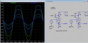
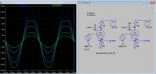
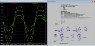
Please take a look at the plate curve below. For some reason, it only plots the first three curves.
I also attached a VM1448 simulation result using Ayumi 6V6 model. It has no problem. When I switched over to your 6V6GT model, I got strange numbers.
Attachments
Last edited:
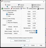
Hi Koonw,In LTSpice, click on Tools->Control Panel->SPICE, change Solver[*] from Normal to Alternate. I have posted this before.
By accident, I found out that the model works with only adding ".option noopiter".
Adding other options listed above will give error results.
Alternate solver is much slower.
Thanks for the support.
Yes, I did notice that the ".options NoOpIter" affects the operating of next Gmin stepping making more details step and eventually revealed failure. Why it happened I don't know. The Gmin and BSource Step makes it slower not the Solver the more steps the slower it is. You can always look at the err.log to see what is going on. The log below shows the details: solver = Alternate is the only one really makes the difference(?).
Circuit: * F:\SIM 2018\last\6v6gt model test.asc
Here is the log without any option showing Gmin is successful but actually not"
.options NoOpIter
.options GminSteps=0
.options SrcSteps=0
Circuit: * F:\SIM 2018\last\6v6gt model test.asc
.step vg=0
.step vg=-5
.step vg=-10
Direct Newton iteration for .op point skipped.
Starting Gmin stepping
Increasing initial diagonal Gmin to 100
Increasing initial diagonal Gmin to 1000
Increasing initial diagonal Gmin to 10000
Increasing initial diagonal Gmin to 100000
Increasing initial diagonal Gmin to 1e+006
Initial Gmin=1e+006 failed
Gmin stepping failed
Starting source stepping with srcstepmethod=0
Source Step = 3.0303%
Source Step = 33.3333%
Source Step = 63.6364%
Source Step = 93.9394%
Source stepping succeeded in finding the operating point.
.step vg=-15
Direct Newton iteration for .op point skipped.
Starting Gmin stepping
Increasing initial diagonal Gmin to 100
Increasing initial diagonal Gmin to 1000
Increasing initial diagonal Gmin to 10000
Increasing initial diagonal Gmin to 100000
Increasing initial diagonal Gmin to 1e+006
Initial Gmin=1e+006 failed
Gmin stepping failed
Starting source stepping with srcstepmethod=0
Source Step = 3.0303%
Source Step = 33.3333%
Source Step = 63.6364%
Source Step = 93.9394%
Source stepping succeeded in finding the operating point.
.step vg=-20
.step vg=-25
.step vg=-30
.step vg=-35
.step vg=-40
.step vg=-45
.step vg=-50
Date: Wed Dec 29 09:20:20 2021
Total elapsed time: 1.847 seconds.
tnom = 27
temp = 27
method = trap
totiter = 24029
traniter = 0
tranpoints = 0
accept = 0
rejected = 0
matrix size = 25
fillins = 17
solver = Alternate
Matrix Compiler1: 1.45 KB object code size 0.4/0.2/[0.1]
Matrix Compiler2: 2.13 KB object code size 0.2/0.3/[0.2]
Here is the log without any option showing Gmin is successful but actually not"
Here using, these option and Solver=Alternate, maybe the best if it works:Circuit: * F:\SIM 2018\last\6v6gt model test.asc
.step vg=0
.step vg=-5
.step vg=-10
Singular matrix: Check nodes va#branch and u1:7
Iteration No. 10
Direct Newton iteration failed to find .op point. (Use ".option noopiter" to skip.)
Starting Gmin stepping
Gmin = 10
Gmin = 1.07374
Gmin = 0.115292
Gmin = 0.0123794
Gmin = 0.00132923
Gmin = 0.000142725
Gmin = 1.5325e-005
Gmin = 1.6455e-006
Gmin = 1.76685e-007
Gmin = 1.89714e-008
Gmin = 2.03704e-009
Gmin = 2.18725e-010
Gmin = 2.34854e-011
Gmin = 2.52173e-012
Gmin = 2.70769e-013
Gmin = 0
Gmin stepping succeeded in finding the operating point.
.step vg=-15
.step vg=-20
.step vg=-25
.step vg=-30
.step vg=-35
.step vg=-40
.step vg=-45
.step vg=-50
Date: Wed Dec 29 10:21:06 2021
Total elapsed time: 2.075 seconds.
tnom = 27
temp = 27
method = trap
totiter = 22676
traniter = 0
tranpoints = 0
accept = 0
rejected = 0
matrix size = 25
fillins = 11
solver = Alternate
Matrix Compiler1: 1.43 KB object code size 0.3/0.2/[0.1]
Matrix Compiler2: 1.98 KB object code size 0.2/0.4/[0.2]
.options NoOpIter
.options GminSteps=0
.options SrcSteps=0
Circuit: * F:\SIM 2018\last\6v6gt model test.asc
.step vg=0
.step vg=-5
.step vg=-10
Direct Newton iteration for .op point skipped.
Gmin stepping method for .op point skipped.
Source stepping method for .op point skipped.
Pseudo Transient succeeded in finding the operating point at 327.69 ms.
.step vg=-15
Direct Newton iteration for .op point skipped.
Gmin stepping method for .op point skipped.
Source stepping method for .op point skipped.
Pseudo Transient succeeded in finding the operating point at 327.69 ms.
.step vg=-20
.step vg=-25
.step vg=-30
.step vg=-35
.step vg=-40
.step vg=-45
.step vg=-50
Date: Wed Dec 29 10:38:21 2021
Total elapsed time: 1.815 seconds.
tnom = 27
temp = 27
method = trap
totiter = 23296
traniter = 0
tranpoints = 0
accept = 0
rejected = 11
matrix size = 25
fillins = 10
solver = Alternate
Matrix Compiler1: 1.35 KB object code size 0.3/0.2/[0.1]
Matrix Compiler2: 1.96 KB object code size 0.2/0.3/[0.2]
Last edited:
Can anyone tell me how to use these subcircuits in LTSpice? I've successfully used some other ones, but when I try to use the 5654 pentode, it generates an error because the model only has four pins. Should I start with a tetrode instead of a pentode?5654/6AK5/6J1 SPICE Models
Triode-Connected
Code:* * Generic triode model: 5654_T_AN * Copyright 2003--2008 by Ayumi Nakabayashi, All rights reserved. * Version 3.10, Generated on Wed Feb 03 16:25:08 2016 * Plate * | Grid * | | Cathode * | | | .SUBCKT 5654_T_AN A G K BGG GG 0 V=V(G,K)+0.2564934 BM1 M1 0 V=(0.020250832*(URAMP(V(A,K))+1e-10))**-1.0936778 BM2 M2 0 V=(0.57832935*(URAMP(V(GG)+URAMP(V(A,K))/20.822386)+1e-10))**2.5936778 BP P 0 V=0.0042701484*(URAMP(V(GG)+URAMP(V(A,K))/36.004374)+1e-10)**1.5 BIK IK 0 V=U(V(GG))*V(P)+(1-U(V(GG)))*0.0030226533*V(M1)*V(M2) BIG IG 0 V=0.0021350742*URAMP(V(G,K))**1.5*(URAMP(V(G,K))/(URAMP(V(A,K))+URAMP(V(G,K)))*1.2+0.4) BIAK A K I=URAMP(V(IK,IG)-URAMP(V(IK,IG)-(0.002314205*URAMP(V(A,K))**1.5)))+1e-10*V(A,K) BIGK G K I=V(IG) * CAPS CGA G A 0.02p CGK G K 4.3p CAK A K 2.4p .ENDS
Pentode
Code:* * Generic pentode model: 5654_AN * Copyright 2003--2008 by Ayumi Nakabayashi, All rights reserved. * Version 3.10, Generated on Wed Feb 03 16:24:50 2016 * Plate * | Screen Grid * | | Control Grid * | | | Cathode * | | | | .SUBCKT 5654_AN A G2 G1 K BGG GG 0 V=V(G1,K)+0.2564934 BM1 M1 0 V=(0.020250832*(URAMP(V(G2,K))+1e-10))**-1.0936778 BM2 M2 0 V=(0.57832935*(URAMP(V(GG)+URAMP(V(G2,K))/20.822386)))**2.5936778 BP P 0 V=0.0042701484*(URAMP(V(GG)+URAMP(V(G2,K))/36.004374))**1.5 BIK IK 0 V=U(V(GG))*V(P)+(1-U(V(GG)))*0.0030226533*V(M1)*V(M2) BIG IG 0 V=0.0021350742*URAMP(V(G1,K))**1.5*(URAMP(V(G1,K))/(URAMP(V(A,K))+URAMP(V(G1,K)))*1.2+0.4) BIK2 IK2 0 V=V(IK,IG)*(1-0.4*(EXP(-URAMP(V(A,K))/URAMP(V(G2,K))*15)-EXP(-15))) BIG2T IG2T 0 V=V(IK2)*(0.76634978*(1-URAMP(V(A,K))/(URAMP(V(A,K))+10))**1.5+0.23365022) BIK3 IK3 0 V=V(IK2)*(URAMP(V(A,K))+3705)/(URAMP(V(G2,K))+3705) BIK4 IK4 0 V=V(IK3)-URAMP(V(IK3)-(0.002314205*(URAMP(V(A,K))+URAMP(URAMP(V(G2,K))-URAMP(V(A,K))))**1.5)) BIP IP 0 V=URAMP(V(IK4,IG2T)-URAMP(V(IK4,IG2T)-(0.002314205*URAMP(V(A,K))**1.5))) BIAK A K I=V(IP)+1e-10*V(A,K) BIG2 G2 K I=URAMP(V(IK4,IP)) BIGK G1 K I=V(IG) * CAPS CGA G1 A 0.02p CGK G1 K 2.6p C12 G1 G2 1.7p CAK A K 2.4p .ENDS
Yes. Most "pentode" models are actually tetrode models. Very few pentode SPICE subcircuits model the suppressor grid. In practice, the suppressor grid is usually connected to the cathode (either internally or externally) and is not normally used as a modulating element.
Last edited:
Thanks. I am trying to make a distortion pedal using 5654 but for some reason I can't get the "cold clipper" stage to work. With a 12AX7 model, if I raise the value of the cathode resistor, I get asymmetrical clipping. But no matter how high I change the value with the 5654, it doesn't clip. Very strange.Yes. Most "pentode" models are actually tetrode models. Very few pentode SPICE subcircuits model the suppressor grid. In practice, the suppressor grid is usually connected to the cathode (either internally or externally) and is not normally used as a modulating element.
- Home
- Amplifiers
- Tubes / Valves
- Vacuum Tube SPICE Models