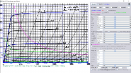
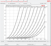
This is 6AN8P model that meet operating points in sch below:
http://www.tubeamp.net/technote6/data/board/kkkgoods/file_in_body/1/magnavox_amp_169aa_286v6_pp29.jpg
http://home.alphalink.com.au/~cambie/6AN8amp/Schematic.gif
http://www.tubeamp.net/technote6/data/board/kkkgoods/file_in_body/1/magnavox_amp_169aa_286v6_pp29.jpg
http://home.alphalink.com.au/~cambie/6AN8amp/Schematic.gif
Code:
* [URL="http://www.dmitrynizh.com/tubeparams_image.htm"]Model Paint Tools: Trace Tube Parameters over Plate Curves, Interactively[/URL]
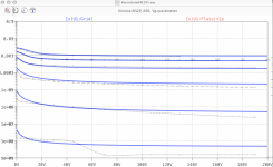
* Plate Curves image file: 6an8p.png
* Data source link: <plate curves URL>
*----------------------------------------------------------------------------------
.SUBCKT 6AN8P P G2 G K ; LTSpice tetrode.asy pinout
* .SUBCKT 6AN8P P G K G2 ; Koren Pentode Pspice pinout
+ PARAMS: MU=45 KG1=621.41 KP=126.12 KVB=7.2 VCT=0.2134 EX=1.391 KG2=2251.15 KNEE=17.21 KVC=2.829
+ KLAM=1.192E-8 KLAMG=6.869E-5 KD=3.151 KC=0.01285 KR1=1.509E-4 KR2=5.3E-5 KVBG=0.01848 KB1=2.138 KB2=1.94 KB3=1.748 KB4=0.5415 KVBGI=0.00108 KNK=0.07988 KNG=0.03636 KNPL=0.03284 KNSL=0.003364 KNPR=11.59 KNSR=24.18
+ CCG=8P CGP=0.04P CCP=3P VGOFF=-1 IGA=4.5E-5 IGB=0.087 IGC=12.64 IGEX=1.54
* Vp_MAX=500 Ip_MAX=35 Vg_step=2 Vg_start=-2.2 Vg_count=10
* X_MIN=29 Y_MIN=27 X_SIZE=832 Y_SIZE=568 FSZ_X=1288 FSZ_Y=723 XYGrid=true
* Rp=1400 Vg_ac=20 P_max=2.3 Vg_qui=-11.2 Vp_qui=300
* showLoadLine=n showIp=y isDHP=n isPP=n isAsymPP=n isUL=n showDissipLimit=y
* showIg1=y isInputSnapped=y addLocalNFB=n
* XYProjections=n harmonicPlot=y dissipPlot=n
* UL=0.43 EG2=150 gridLevel2=y addKink=y isTanhKnee=n advSigmoid=y
*----------------------------------------------------------------------------------
RE1 7 0 1G ; DUMMY SO NODE 7 HAS 2 CONNECTIONS
E1 7 0 VALUE= ; E1 BREAKS UP LONG EQUATION FOR G1.
+{V(G2,K)/KP*LOG(1+EXP((1/MU+(VCT+V(G,K))/SQRT(KVB+V(G2,K)*V(G2,K)))*KP))}
RE2 6 0 1G ; DUMMY SO NODE 6 HAS 2 CONNECTIONS
E2 6 0 VALUE={(PWR(V(7),EX)+PWRS(V(7),EX))} ; Kg1 times KIT current
E4 8 0 VALUE={V(P,K)/KNEE/(KVBGI+V(6)*KVBG)}
E5 81 0 VALUE={PWR(V(8),KB1)}
E6 82 0 VALUE={PWR(V(8),KB2)}
E7 83 0 VALUE={PWR(V(8),KB3)}
E8 9 0 VALUE={PWR(1-EXP(-V(81)*(KC+KR1*V(82))/(KD+KR2*V(83))),KB4)*1.5708}
RE4 8 0 1
RE5 81 0 1
RE6 82 0 1
RE7 83 0 1
RE8 9 0 1
RE21 21 0 1
E21 21 0 VALUE={V(6)/KG1*V(9)} ; Ip with knee but no slope and no kink
RE22 22 0 1 ; E22: kink curr deviation for plate
E22 22 0 VALUE={V(21)*LIMIT(KNK-V(G,K)*KNG,0,0.3)*(-ATAN((V(P,K)-KNPL)/KNSL)+ATAN((V(P,K)-KNPR)/KNSR))}
G1 P K VALUE={V(21)*(1+KLAMG*V(P,K))+KLAM*V(P,K) + V(22)}
G2 G2 K VALUE={V(6)/KG2*(KVC-V(9))/(1+KLAMG*V(P,K)) - V(22)}
RCP P K 1G ; FOR CONVERGENCE
C1 K G {CCG} ; CATHODE-GRID 1
C2 G P {CGP} ; GRID 1-PLATE
C3 K P {CCP} ; CATHODE-PLATE
RE23 G 0 1G
GG G K VALUE={(IGA+IGB/(IGC+V(P,K)))*(MU/KG1)*
+(PWR(V(G,K)-VGOFF,IGEX)+PWRS(V(G,K)-VGOFF,IGEX))}
.ENDS
*$Attachments
Last edited:
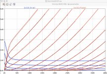
This is everything I've collected for 6C45P (6S45P). I don't have any of those tubes, so I can't tell you which (if any) of these are particularly accurate. I understand the tubes themselves have quite variable characteristics, which would make it difficult to create a one-size-fits-most model. Hopefully one of these models will work well enough for you.
No wonder Eli Duttman called it a "firecracker" tube.


Thanks for those curves!
The spread is large at 60mA and 250 to 275V.
But that is 15 to 16.5 Watts, great for transient conditions like curve tracing.
When I used them, it was at 10mA, and the plate voltage spread is about 25 Volts with fixed bias.
I used self bias, and it was close to 2.5V.
I either used them as a self biased single triode gain stage,
Or as a cathode coupled phase splitter with a current source to the cathodes.
They worked real good in those 2 applications, but for the phase splitter, you need to find a matched pair.
I did not use them as cathode followers.
Last edited:
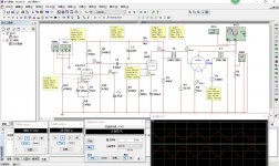
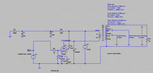
I'm starting to get to grips with ltspice and trying to use it to fill in some question marks in the schematic of a 1940's PA amp I'm trying to get operational again.
The amp looked deceptively simple, and I made notes regarding the connections between the subcomponents, but must have screwed up somewhere because the schematic does not make a lot of sense.
Anyway, it uses a triode wired EF12 for the first stage, an EF12 pentode as driver, and EL11 single ended output.
I think I can use an EL41 model for the EL11, and I have that, but I cannot find models for the EF12's. They are not a million miles from an EF86, so I've tried that, but cannot get the operating point correct.
Is there a method to approximate the operating characteristics in a model to adapt it to another tube? I've been looking today, and it is not as obvious as I hoped.
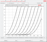
Try this for EF12:
Code:
**** EF12 ******************************************
* Created on 01/30/2021 22:34 using paint_kip.jar
* [url=http://www.dmitrynizh.com/tubeparams_image.htm]Model Paint Tools: Trace Tube Parameters over Plate Curves, Interactively[/url]
* Plate Curves image file:
* Data source link: <plate curves URL>
*----------------------------------------------------------------------------------
.SUBCKT EF12 P G2 G K ; LTSpice tetrode.asy pinout

+ PARAMS: MU=29.23 KG1=1760 KP=148.66 KVB=3.51 VCT=0.006625 EX=1.276 KG2=3948.42 KNEE=7.14 KVC=2.57
+ KLAM=9.668E-11 KLAMG=1.312E-5 KNEE2=29.6 KNEX=24.3  KNK=-0.05148 KNG=0.00642 KNPL=43 KNSL=1.018 KNPR=100.8 KNSR=5.003
+ CCG=6.5P CGP=0.002P CCP=6.5P RGI=2000.0
* Vp_MAX=450 Ip_MAX=10 Vg_step=0.5 Vg_start=0 Vg_count=9
* X_MIN=111 Y_MIN=109 X_SIZE=575 Y_SIZE=639 FSZ_X=1278 FSZ_Y=833 XYGrid=true
* Rp=1400 Vg_ac=20 P_max=1.5 Vg_qui=-2 Vp_qui=300
* showLoadLine=y showIp=y isDHP=n isPP=n isAsymPP=n isUL=n showDissipLimit=y
* showIg1=n isInputSnapped=y addLocalNFB=n
* XYProjections=n harmonicPlot=y dissipPlot=n
* UL=0.43 EG2=100 gridLevel2=n addKink=y isTanhKnee=y advSigmoid=n
*----------------------------------------------------------------------------------
RE1  7 0  1G    ; DUMMY SO NODE 7 HAS 2 CONNECTIONS
E1   7 0  VALUE=  ; E1 BREAKS UP LONG EQUATION FOR G1.
+{V(G2,K)/KP*LOG(1+EXP((1/MU+(VCT+V(G,K))/SQRT(KVB+V(G2,K)*V(G2,K)))*KP))}
RE2  6 0  1G    ; DUMMY SO NODE 6 HAS 2 CONNECTIONS
E2  6 0  VALUE={(PWR(V(7),EX)+PWRS(V(7),EX))} ; Kg1 times KIT current
RE21 21 0 1
E21  21 0 VALUE={V(6)/KG1*ATAN((V(P,K)+KNEX)/KNEE)*TANH(V(P,K)/KNEE2)} ; Ip with knee but no slope and no kink
RE22 22 0 1 ; E22: kink curr deviation for plate
E22  22 0 VALUE={V(21)*LIMIT(KNK-V(G,K)*KNG,0,0.3)*(-ATAN((V(P,K)-KNPL)/KNSL)+ATAN((V(P,K)-KNPR)/KNSR))}
G1   P  K  VALUE={V(21)*(1+KLAMG*V(P,K))+KLAM*V(P,K) + V(22)}
* Alexander Gurskii screen current, see audioXpress 2/2011, with slope and kink added
RE43 43 K 1G ; Dummy
E43  43 G2 VALUE={0} ; Dummy
G2   43 K  VALUE={V(6)/KG2*(KVC-ATAN((V(P,K)+KNEX)/KNEE)*TANH(V(P,K)/KNEE2))/(1+KLAMG*V(P,K))-V(22)}
RCP  P K  1G     ; FOR CONVERGENCE
C1   K G  {CCG}  ; CATHODE-GRID 1
C2   G P  {CGP}  ; GRID 1-PLATE
C3   K P  {CCP}  ; CATHODE-PLATE
R1   G 5  {RGI}  ; FOR GRID CURRENT
D3   5 K  DX     ; FOR GRID CURRENT }
.MODEL DX D(IS=1N RS=1 CJO=10PF TT=1N)
.ENDS(...) For NOS soviet tubes, I plan to do: 6N1P, 6N2P (6N3P already done) 6N15P, 6N16B, hope fully 6N17B-V (deal in progress)
Hi all,
just want to announce a "close-to-reality" 6N2P spice model. I have 5 tubes burning in now, reaching the goal of 100 hours this weekend. Measurements, golden Sample selection and spice model creation will follow during the next days...
")
cheers, Adrian
Attachments
Last edited:
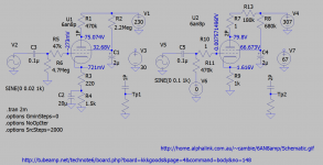
Building up a model to emulate an existing circuit
Plea for help!
Recently I modelled a Consonance T1 preamplifier in LTSpice, and was very impressed when I managed to get almost identical operating data from the amplifier as was predicted in the model.
As mentioned in an earlier post, I was a bit hasty dismantling an old PA amplifier, and I would like to rebuild it with the same operating points, but there are some aspects of the schema I derived that don't appear to make sense.
The more I look into these old circuits from the 40's, many of them seem to have additional complexity to overcome weaknesses in the components that were being used. For instance, fixes for stability due to poor quality output transformers, and subtle forms of feedback to improve linearity.
I would very much like to be able to understand this old circuit from the 40's, and coming from an IT background, that means I need to be able to model it so I can emulate the contributions of the different design elements.
The output tube is a single ended EL11, which is identical to an EL41 in characteristics. I have sourced a model for the transformer, and I am trying to build the model up from the ground up.
What I am aiming for is a model of the output stage, where I can emulate the signal to the grid of the output tube, and measure the voltage on the speakers.
I cannot get the model below to work, and I know I am missing something obvious in my basic understanding of LT Spice. Not being an electronics engineer, the effects of impedance and reactance are not as obvious as resiatance and capacitance, so I think it is highlighting my general lack of understanding of circuitry.
However, the models I am using are also untested in some ways, so I also lack a bit of confidence in relying too strongly in the modelling.
Below is the model I am using. Any pointers greatly appreciated!
Code:
******************
.SUBCKT EL41  1 2 3 4 ; A G2 G1 K (Pentode) AKA BF61 N150 6CK5
* Philips data sheet
* library format: LTSpice 16-Nov-2009
X1 1 2 3 4 EL80 ; Call EL80
.ENDS    EL41

******************
.SUBCKT EL80  1 2 3 4 ; A G2 G1 K (Pentode)
* Philips data sheet
* library format: LTSpice 16-Nov-2009
X1 1 2 3 4 PENTODE1 MU=24.38 EX=1.084 KG1=292.0 KG2=4500 KP=153.56 KVB=26.2 VCT=0.00 RGI=2000 CCG=4.3p CPG1=0.6p CCP=5.1p ;
.ENDS    EL80

******************
.SUBCKT PENTODE1 1 2 3 4 ; A G2 G1 K
RE1  7 0  1MEG    ; DUMMY SO NODE 7 HAS 2 CONNECTIONS
E1   7 0  VALUE={V(2,4)/KP*LOG(1+EXP((1/MU+V(3,4)/V(2,4))*KP))}	; E1 BREAKS UP LONG EQUATION FOR G1.
G1   1 4  VALUE={(PWR(V(7),EX)+PWRS(V(7),EX))/KG1*ATAN(V(1,4)/KVB)}
G2   2 4  VALUE={(EXP(EX*(LOG((V(2,4)/MU)+V(3,4)))))/KG2}
*G2   2 4  VALUE={PWR(if( V(2,4)/MU+V(3,4) < 0 , V(2,4)/MU+V(3,4), 0 ) ,EX )/KG2}
RCP  1 4  1G      ; FOR CONVERGENCE	A  - C
C1   3 4  {CCG}   ; CATHODE-GRID 1	C  - G1
C2   1 3  {CPG1}  ; GRID 1-PLATE	G1 - A
C3   1 4  {CCP}   ; CATHODE-PLATE	A  - C
R1   3 5  {RGI}   ; FOR GRID CURRENT	G1 - 5
D3   5 4  DX      ; FOR GRID CURRENT	5  - C
.MODEL DX D(IS=1N RS=1 CJO=10PF TT=1N) ;
.ENDS PENTODE1
Attachments
Try this for EF12:
Thanks for that! I managed to emulate the input stage, but now I am struggling linking stages together, as described in my post earlier today.
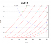
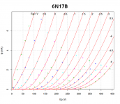
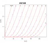
A new member, pcardoso73, posted a request for LTspice models for the following tubes: 6N16B, 6N17B, 6N21B and 6S31B here. I would much rather post them here. I don't have the model for 6S31B, but I have the others. Here we go...
Code:
* ==============================================================
* 6N16B LTSpice model
* Modified Koren model (8 parameters): mean fit error 0.192445mA
* Traced by Wayne Clay on 09/19/2018 using Engauge Digitizer and
* Curve Captor v0.9.1 from Soviet data sheet
* ==============================================================
.subckt 6N16B  P G K
    Bp  P K  I=
+ (0.005806558558m)*uramp(V(P,K)*ln(1.0+(0.07417944543)+exp((7.059640136)+
+ (7.059640136)*((26.17659172)+(213.8309805m)*V(G,K))*V(G,K)/sqrt((29.16492618)**2+
+ (V(P,K)-(1.416531025))**2)))/(7.059640136))**(1.769180029)
    Cgp G P  1.7p ; 0.2p added (1.5p)
    Cgk G K  3.4p ; 0.7p added (2.7p)
    Cpk P K  1.85p ; 0.2p added (1.65p)
    Rpk P K  1G ; to avoid floating nodes
    d3  G K  dx1
.model dx1 d(is=1n rs=2k cjo=1pf N=1.5 tt=1n)
.ends 6N16B

* ==============================================================
*
* Generic triode model: 6N16B_AN
* Copyright 2003--2008 by Ayumi Nakabayashi, All rights reserved.
* Version 3.10, Generated on Wed Sep 19 13:32:09 2018
*                Plate
*                | Grid
*                | | Cathode
*                | | |
.SUBCKT 6N16B_AN A G K
BGG   GG   0 V=V(G,K)+-0.22873155
BM1   M1   0 V=(0.013386971*(URAMP(V(A,K))+1e-10))**-0.56148061
BM2   M2   0 V=(0.72763236*(URAMP(V(GG)+URAMP(V(A,K))/20.345726)+1e-10))**2.0614806
BP    P    0 V=0.0030235941*(URAMP(V(GG)+URAMP(V(A,K))/27.961546)+1e-10)**1.5
BIK   IK   0 V=U(V(GG))*V(P)+(1-U(V(GG)))*0.0017414379*V(M1)*V(M2)
BIG   IG   0 V=0.0015117971*URAMP(V(G,K))**1.5*(URAMP(V(G,K))/(URAMP(V(A,K))+URAMP(V(G,K)))*1.2+0.4)
BIAK  A    K I=URAMP(V(IK,IG)-URAMP(V(IK,IG)-(0.0016754397*URAMP(V(A,K))**1.5)))+1e-10*V(A,K)
BIGK  G    K I=V(IG)
* CAPS
CGA   G    A 1.5p
CGK   G    K 2.7p
CAK   A    K 1.7p
.ENDS

* ==============================================================
* 6N17B LTSpice model
* Modified Koren model (8 parameters): mean fit error 0.0935463mA
* Traced by Wayne Clay on 10/10/2018 using Engauge Digitizer and
* Curve Captor v0.9.1 from Soviet data sheet
* ==============================================================
.subckt 6N17B  P G K
    Bp  P K  I=
+ (8.881819189e-05m)*uramp(V(P,K)*ln(1.0+(-0.05787376447)+exp((0.7467399581)+
+ (0.7467399581)*((266.0580109)+(3397.261292m)*V(G,K))*V(G,K)/sqrt((-0.6714542748)**2+
+ (V(P,K)-(-63.58379404))**2)))/(0.7467399581))**(2.021894)
    Cgp G P  1.8p ; 0.2p added (1.6p)
    Cgk G K  3.6p ; 0.7p added (2.9p)
    Cpk P K  1.9p ; 0.2p added (1.7p)
    Rpk P K  1G ; to avoid floating nodes
    d3  G K  dx1
.model dx1 d(is=1n rs=2k cjo=1pf N=1.5 tt=1n)
.ends 6N17B

* ==============================================================
*
* Generic triode model: 6N17B_AN
* Copyright 2003--2008 by Ayumi Nakabayashi, All rights reserved.
* Version 3.10, Generated on Fri Oct 12 14:46:37 2018
*                Plate
*                | Grid
*                | | Cathode
*                | | |
.SUBCKT 6N17B_AN A G K
BGG   GG   0 V=V(G,K)+-0.35544294
BM1   M1   0 V=(0.01291172*(URAMP(V(A,K))+1e-10))**-2.0483062
BM2   M2   0 V=(0.42273692*(URAMP(V(GG)+URAMP(V(A,K))/44.708457)+1e-10))**3.5483062
BP    P    0 V=0.0043126487*(URAMP(V(GG)+URAMP(V(A,K))/105.75953)+1e-10)**1.5
BIK   IK   0 V=U(V(GG))*V(P)+(1-U(V(GG)))*0.0081637051*V(M1)*V(M2)
BIG   IG   0 V=0.0021563244*URAMP(V(G,K))**1.5*(URAMP(V(G,K))/(URAMP(V(A,K))+URAMP(V(G,K)))*1.2+0.4)
BIAK  A    K I=URAMP(V(IK,IG)-URAMP(V(IK,IG)-(0.0022176355*URAMP(V(A,K))**1.5)))+1e-10*V(A,K)
BIGK  G    K I=V(IG)
* CAPS
CGA   G    A 1.6p
CGK   G    K 2.9p
CAK   A    K 1.7p
.ENDS

* ==============================================================
* 6N21B LTSpice model
* Modified Koren model (6 parameters): mean fit error 0.164874mA
* Traced by Wayne Clay on 02/03/21 using Engauge 10.10 and
* Curve Captor v0.9.1 from Soviet datasheet
* ==============================================================
.subckt 6N21B  P G K
    Bp  P K  I=
+ (0.01585763164m)*uramp(V(P,K)*ln(1.0+(-0.03314981701)+exp((1.324792497)+
+ (1.324792497)*((147.6480975)+(-8815.012037m)*V(G,K))*
+ V(G,K)/V(P,K)))/(1.324792497))**(1.201675123)
    Cgp G P 1.4p
    Cgk G K 2.7p
    Cpk P K 1.65p
    Rpk P K 1.0G ; to avoid floating nodes in mu-follower
    d3  G K dx1
.model dx1 d(is=1n rs=2k cjo=1pf N=1.5 tt=1n)
.ends 6N21B

* ==============================================================
*
* Generic triode model: 6N21B_AN
* Copyright 2003--2008 by Ayumi Nakabayashi, All rights reserved.
* Version 3.10, Generated on Wed Feb  3 22:27:37 2021
*                Plate
*                | Grid
*                | | Cathode
*                | | |
.SUBCKT 6N21B_AN A G K
BGG   GG   0 V=V(G,K)+0.22747067
BM1   M1   0 V=(0.011576495*(URAMP(V(A,K))+1e-10))**-1.7714952
BM2   M2   0 V=(0.45850595*(URAMP(V(GG)+URAMP(V(A,K))/46.775303)+1e-10))**3.2714952
BP    P    0 V=0.0035387805*(URAMP(V(GG)+URAMP(V(A,K))/102.01679)+1e-10)**1.5
BIK   IK   0 V=U(V(GG))*V(P)+(1-U(V(GG)))*0.004751622*V(M1)*V(M2)
BIG   IG   0 V=0.0017693902*URAMP(V(G,K))**1.5*(URAMP(V(G,K))/(URAMP(V(A,K))+URAMP(V(G,K)))*1.2+0.4)
BIAK  A    K I=URAMP(V(IK,IG)-URAMP(V(IK,IG)-(0.0018215499*URAMP(V(A,K))**1.5)))+1e-10*V(A,K)
BIGK  G    K I=V(IG)
* CAPS
CGA   G    A 1.4p
CGK   G    K 2.7p
CAK   A    K 1.7p
.ENDS
Attachments
Hi all,
as announced in #2811, here is my "close to reality" 6N2P spice model. The 5 samples I burnt in showed surprisingly low manufacturing tolerances in terms of mu and gm. The contact voltage varies a bit, but it is less than +/- 0.3V.
The differences to the data sheet are not as dramatic as it was for the 6N1P.
However, here is the model:
cheers, Adrian
as announced in #2811, here is my "close to reality" 6N2P spice model. The 5 samples I burnt in showed surprisingly low manufacturing tolerances in terms of mu and gm. The contact voltage varies a bit, but it is less than +/- 0.3V.
The differences to the data sheet are not as dramatic as it was for the 6N1P.
However, here is the model:
Code:
*6N2P LTspice model based on the generic triode model from Adrian Immler, version i4
*A version log is at the end of this file
*100h BurnIn of 5 Voskhod factory tubes, sample selection and measurements done in Febr. 2021
*Params fitted to the measured values by Adrian Immler, Febr. 2021
*The high fit quality is presented at adrianimmler.simplesite.com
*History's best of tube decribing art (plus some new ideas) is merged to this new approach.
*@ neg. Vg, Ia accuracy is similar to Koren models.
*@ small neg. Vg, the "Anlauf" current is considered.
*@ pos. Vg, Ig and Ia accuracy is on a unrivaled level.
*This offers new simulation possibilities like bias point setting with MOhm grid resistor,
*Audion radio circuits, low voltage amps, guitar distortion stages or pulsed stages.
* anode (plate)
* | grid
* | | cathode
* | | |
.subckt 6N2P.i4 A G K
+ params:
*Parameters for the space charge current @ Vg <= 0
+ mu = 109.2;Determines the voltage gain @ constant Ia
+ rad = 48k3 ;Differential anode resistance, set @ Iad and Vg=0V
+ Vct = 0.31 ;Offsets the Ia-traces on the Va axis. Electrode material's contact potential
+ kp = 391 ;Mimics the island effect
+ xs = 1.56 ;Determines the curve of the Ia traces. Typically between 1.2 and 1.8
*
*Parameters for assigning the space charge current to Ia and Ig @ Vg > 0
+ kB = 0.36 ;Describes how fast Ia drops to zero when Va approaches zero.
+ radl = 2960 ;Differential resistance for the Ia emission limit @ very small Va and Vg > 0
+ tsh = 5 ;Ia transmission sharpness from 1th to 2nd Ia area. Keep between 3 and 20. Start with 20.
+ xl = 1.2 ;Exponent for the emission limit
*
*Parameters of the grid-cathode vacuum diode
+ kvdg = 122 ;virtual vacuumdiode. Causes an Ia reduction @ Ig > 0.
+ kg = 2295 ;Inverse scaling factor for the Va independent part of Ig (caution - interacts with xg!)
+ Vctg = 0.05 ;Offsets the log Ig-traces on the Vg axis. Electrode material's contact potential
+ xg = 1.7 ;Determines the curve of the Ig slope versus (positive) Vg and Va >> 0
+ VT = 0.11 ;Log(Ig) slope @ Vg<0. VT=k/q*Tk (cathodes absolute temp, typically 1150K)
+ kVT=0 ;Va dependant koeff. of VT
+ Vft2 = 0 gft2 = 0 ;finetunes the gridcurrent @ low Va and Vg near zero
*
*Parameters for the caps
+ cag = 0p7 ;From datasheet
+ cak = 2p5 ;From datasheet
+ cgk = 2p25 ;From datasheet
*
*special purpose parameters
+ os = 1 ;Overall scaling factor, if a user wishes to simulate manufacturing tolerances
*
*Calculated parameters
+ Iad = {100/rad} ;Ia where the anode a.c. resistance is set according to rad.
+ ks = {pow(mu/(rad*xs*Iad**(1-1/xs)),-xs)} ;Reduces the unwished xs influence to the Ia slope
+ ksnom = {pow(mu/(rad*1.5*Iad**(1-1/1.5)),-1.5)} ;Sub-equation for calculating Vg0
+ Vg0 = {Vct + (Iad*ks)**(1/xs) - (Iad*ksnom)**(2/3)} ;Reduces the xs influence to Vct.
+ kl = {pow(1/(radl*xl*Ild**(1-1/xl)),-xl)} ;Reduces the xl influence to the Ia slope @ small Va
+ Ild = {sqrt(radl)*1m} ;Current where the Il a.c. resistance is set according to radl.
*
*Space charge current model
Bggi GGi 0 V=v(Gi,K)+Vg0 ;Effective internal grid voltage.
Bahc Ahc 0 V=uramp(v(A,K)) ;Anode voltage, hard cut to zero @ neg. value
Bst St 0 V=uramp(max(v(GGi)+v(A,K)/(mu), v(A,K)/kp*ln(1+exp(kp*(1/mu+v(GGi)/(1+v(Ahc)))))));Steering volt.
Bs Ai K I=os/ks*pow(v(St),xs) ;Langmuir-Childs law for the space charge current Is
*
*Anode current limit @ small Va
.func smin(z,y,k) {pow(pow(z+1f, -k)+pow(y+1f, -k), -1/k)} ;Min-function with smooth trans.
Ra A Ai 1
Bgl Gi A I=min(i(Ra)-smin(1/kl*pow(v(Ahc),xl),i(Ra),tsh),i(Bgvd)*exp(4*v(G,K))) ;Ia emission limit
*
*Grid model
Bvdg G Gi I=1/kvdg*pwrs(v(G,Gi),1.5) ;Reduces the internal effective grid voltage when Ig rises
Rgip G Gi 1G ;avoids some warnings
Cvdg G Gi 0p1;this small cap improves convergence
.func fVT() {VT*exp(-kVT*sqrt(v(A,K)))}
.func Ivd(Vvd, kvd, xvd, VTvd) {if(Vvd < 3, 1/kvd*pow(VTvd*xvd*ln(1+exp(Vvd/VTvd/xvd)),xvd), 1/kvd*pow(Vvd, xvd))} ;Vacuum diode function
Bgvd Gi K I=Ivd(v(G,K) + Vctg, kg/os, xg, fVT())
.func ft2() {gft2*(1-tanh(3*(v(G,K)+Vft2)))} ;Finetuning-func. improves ig-fit @ Vg near -0.5V, low Va.
Bgr Gi Ai I=ivd(v(GGi),ks/os, xs, 0.8*VT)/(1+ft2()+kB*v(Ahc));Is reflection to grid when Va approaches zero
Bs0 Ai K I=ivd(v(GGi),ks/os, xs, 0.8*VT)/(1+ft2()) - os/ks*pow(v(GGi),xs) ;Compensates neg Ia @ small Va and Vg near zero
*
*Caps
C1 A G {cag}
C2 A K {cak}
C3 G K {cgk}
.ends
*
*Version log
*i1 :Initial version
*i2 :Pin order changed to the more common order âA G Kâ (Thanks to Markus Gyger for his tip)
*i3 :bugfix of the Ivd-function: now also usable for larger Vvd
*i4: Rgi replaced by a virtual vacuum diode (better convergence). ft1 deleted (no longer needed)
;2 new prarams for Ig finetuning @ Va and Vg near zero. New emission skaling factor ke for aging etc.cheers, Adrian
Attachments
- Home
- Amplifiers
- Tubes / Valves
- Vacuum Tube SPICE Models